 Jesse Farrell
Hardware Bug Fixes & Lessons Learned - REV00 Sparkup
Bringing up a new revision always reveals some new bugs. While the core logic of REV00 is solid, I’ve had to perform some bodge work to get the system fully operational. Here is the breakdown of the primary issues discovered during bench testing (in no particular order). Items below are all listed in my REV00 errata, and have been addressed by my REV01 update.
UPDI Programming Header
This was an easy one... I neglected the pull-up resistor on the UPDI line. Easy to solve with a 10k.
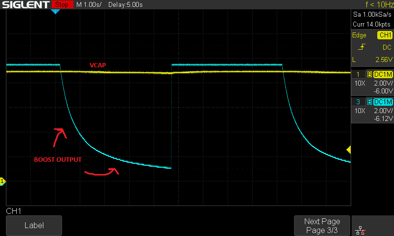
Boost Converter Leakage
While testing the drain on my pulse energy storage circuit I noticed self discharge was much greater than expected. Current was either leaking back into the boost converter output or across the H-bridge.
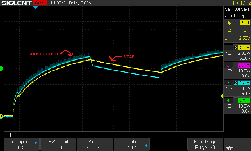
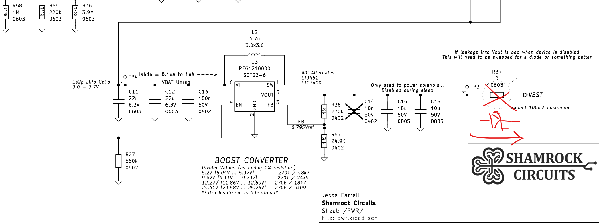
Luckily past me saved present me's bacon. Somewhat anticipating this issue, I added a 0ohm resistor at the boost converter output. Replacing the 0ohm 0603 with a Schottky resolved the issue.
Now when the boost converter is disabled the voltage across the capacitor holds steady.
VSTOR Loading & Startup Issues
The system refused to boot from VBAT. Whether I simulated an "already charged" battery, or if I allowed the system to charge the battery itself, VSTOR refused to come up. Instead getting stuck around 1.6V.
I initially suspected my voltage divider values on the TI BQ25504, but they seemed to match the schematic. After some datasheet sniffing, I found a critical note.
If a system load tied to VSTOR discharges VSTOR below VSTOR_GEN or below VBAT_UV during the 32 ms initial MPPT reference voltage measurement or within 110 ms after hot plug, it is recommended to add an external PFET between the system load and VSTOR
It seems like the BQ25504 is extremely sensitive to VSTOR loading during startup. I found that if I hold the solar panel directly against a bright light source, it drives VSTOR hard enough to overcome the meek ATTINY load. Once the system is past that 110ms window and fully booted, it functions normally without the extra light.
The datasheet recommends adding an external PFET between the system load and VSTOR to keep the rail isolated until VSTOR is stable. I'll be implementing that to ensure the system can boot on REV01.
ADC Overvoltage
This was a "head-in-hands" moment during sparkup. I designed a voltage divider to measure the 24V VCAP signal, but I used a low-side switch (SNS_VBST_EN) to enable the measurement.
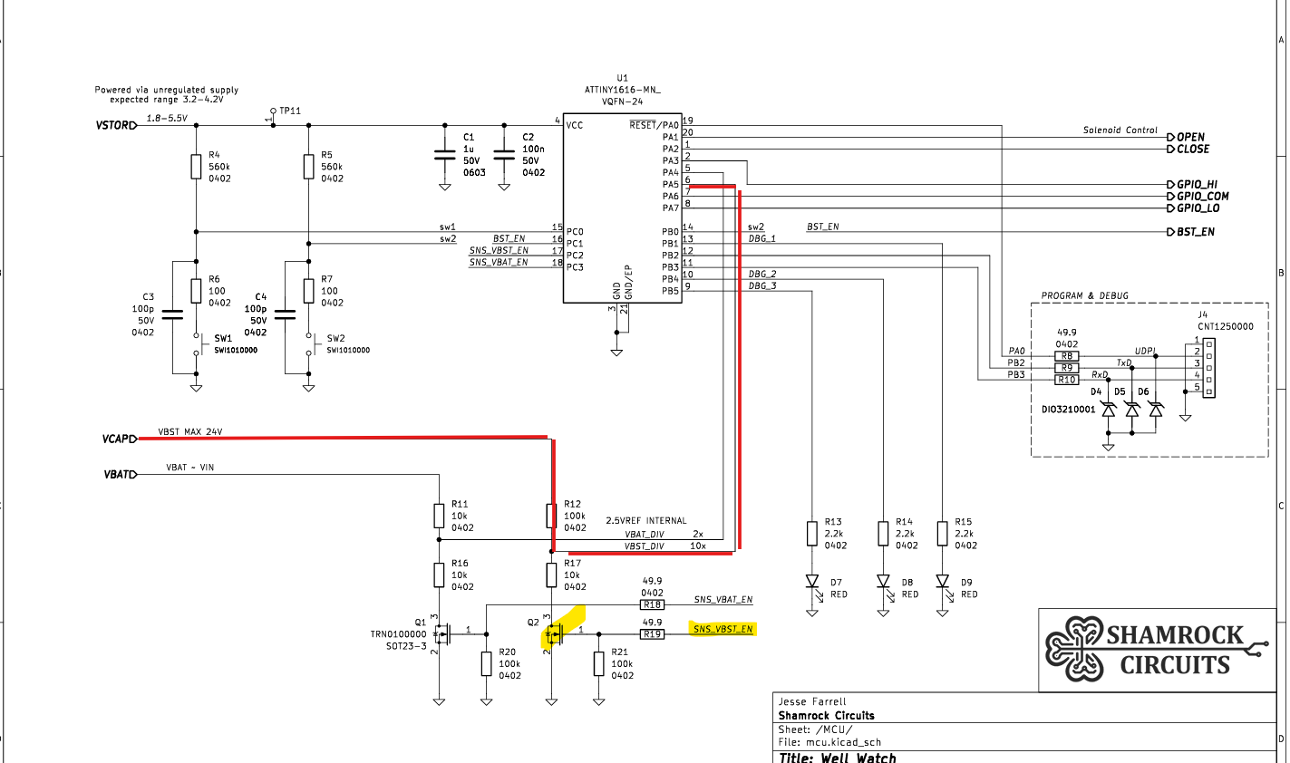
When the low-side switch is OFF, the bottom of the divider floats, and the ATtiny1616 sees the full 24V signal (heavily current-limited, but still). I essentially slapped a high-voltage rail directly into a 3V GPIO. Probing VBST_DIV showed it pulled to VCC (3V), meaning the internal ESD diodes on PA5 were working overtime sinking about 60uA. Not ideal for long-term reliability or power consumption.
For the next spin, I’ve added a high-side switch with an NMOS driver. Because of the double inversion in the hardware, the firmware logic remains identical. Easy peezy.
Discussions
Become a Hackaday.io Member
Create an account to leave a comment. Already have an account? Log In.