 Tom Nardi
The first version of a PCB almost always has some issues that can be improved on, but in this case, V1 of the badge was a real dog.
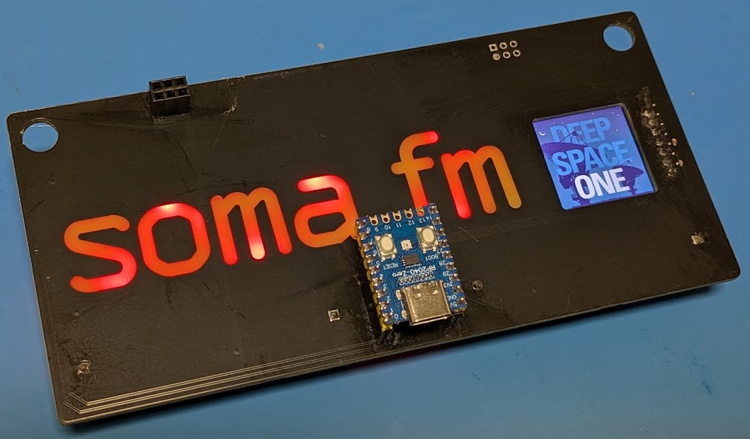
I'd love to tell you that this was some clever "development version" that has the RP2040 Zero in a socket on the front for easy debugging....but no. I just never flipped its footprint to the backside of the board, and since I didn't have any 3D model assigned for it in KiCAD, it was never obvious in the board previews. Oops.
But wait, it gets better!
Not only did I have the pin layout for the MCU inverted, I also managed to flip around the clock and data pins for the display.
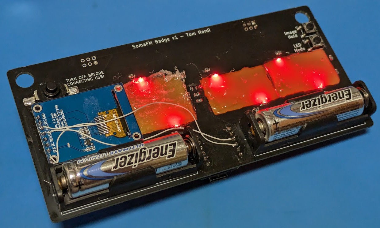
But while this version of the badge obviously needed some work, it did give me something to develop the firmware on while I was working on the V2 layout. It also showed that using clear hot glue to spread out the light from the LEDs would work nicely -- though that being said, I did decide to double the number of LEDs on V2 of the badge to provide more even illumination.
Discussions
Become a Hackaday.io Member
Create an account to leave a comment. Already have an account? Log In.