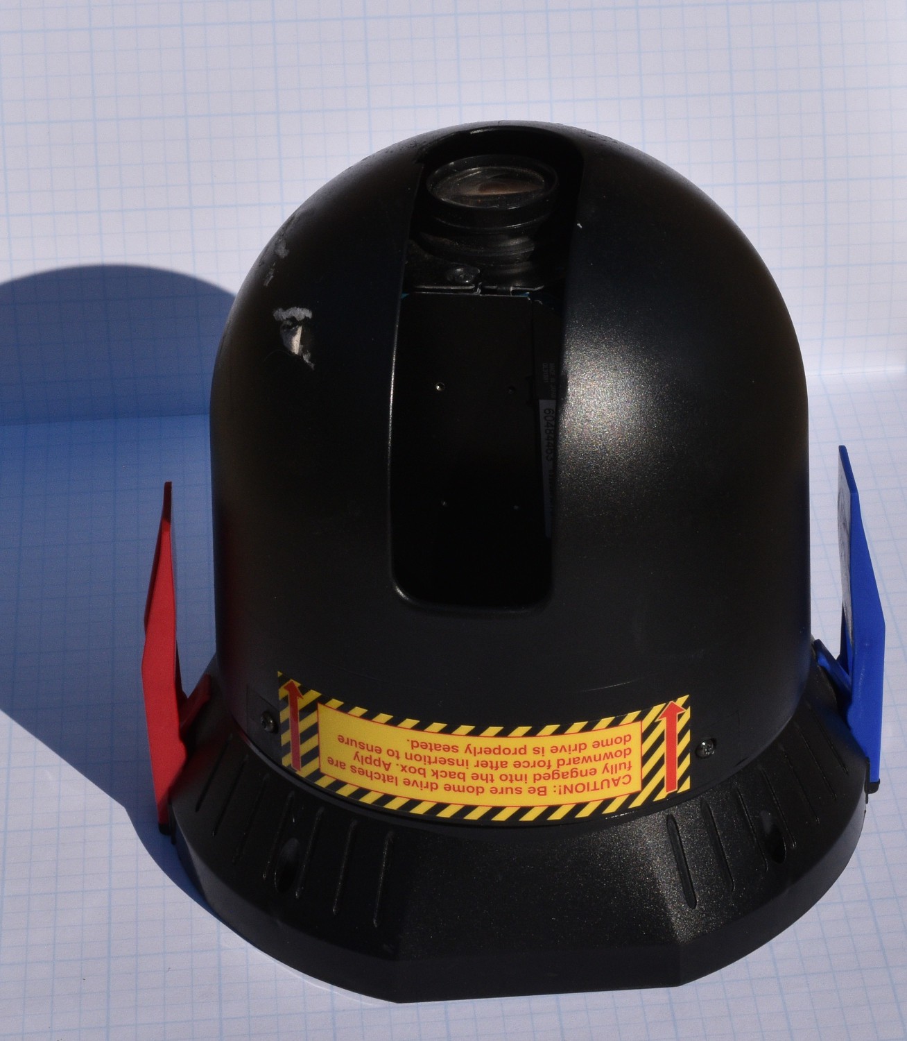
Pelco dome cameras look like this:

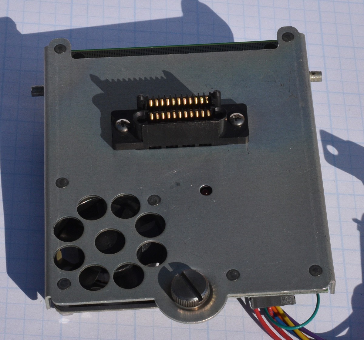
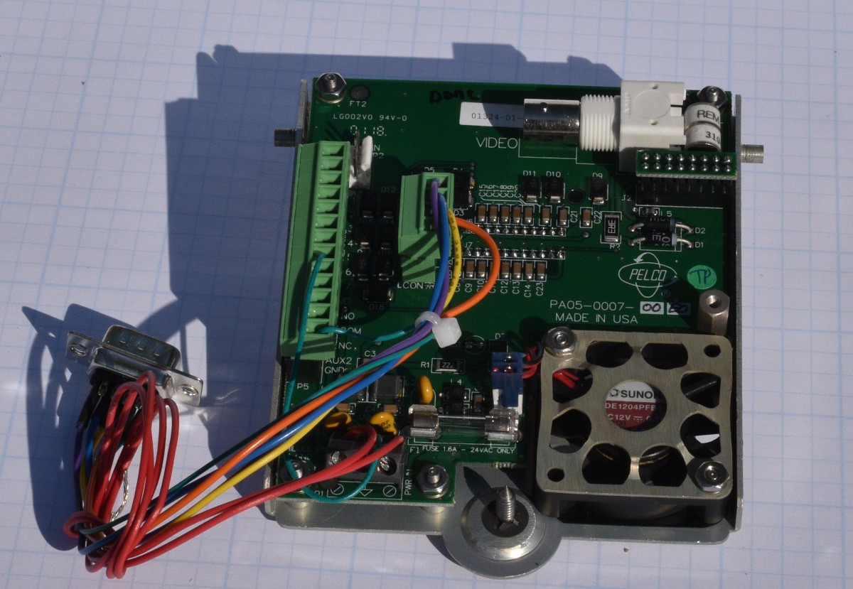
The camera shown snaps into an enclosure with a "base board". The base board breaks out the proprietary connector on the bottom of the camera into terminal strips for connecting to the building wiring. The base board also controls fans and heaters for outdoor use, and has lots of TVS diodes for protecting the camera electronics from electrical transients related to long cable runs.


The cameras run on about 24 Volts AC, with the AC line frequency used to synchronize the video framing. This is pretty common in analog surveilance cameras because it allows all of the cameras in a building to be synchronized with each other. This is not an issue with newer IP network cameras, but old school analog cameras needed to be synchronized to allow smoothly switching from camera to camera without complex hardware.
When I got the cameras, they did not come with any enclosures or the baseboards.Starting with the camera in the worst mechanical condition, I reverse engineered enough of the wiring to the connector on the bottom of the camera to hook up power, video and the RS422 signals. I spliced into those wires for testing. I was pleased to see that even the beat up camera would power up, initialize and output video. Once I verified that the cameras appeared to mostly work, I bought a couple of the base boards on the used market so I would not have to cut up the other cameras.
Communications with the camera is done with the RS422/485 physical layer protocol at 2400 Bits/Second no parity and one stop bit. In a past project, I built some USB to RS422/485 boards and had one left over. They are simple, a USB UART chip (FTDI FT230X), an RS422/485 transceiver chip (MAX3086CSD+), a few passives and a connector. FTDI also sells some nicely packaged dongles for this if you don't want to build your own.
Pelco's communication protocol for controlling cameras is called Pelco D Protocol. Searching the net for documents on the Pelco D Protocol turned up an 8 page document that identified the bits and bytes of the protocol, but nothing about how to use it. This document is titled "D Protocol Manual, released March 2 1999.
The protocol in this document looks like it was built in at least 2 iterations. All of the commands are built with 7 bytes:
| Byte 1 | Byte 2 | Byte 3 | Byte 4 | Byte 5 | Byte 6 | Byte 7 |
| Sync Byte 0xFF | Camera Address | Command Byte 1 | Command Byte 2 | Data Byte 1 | Data Byte 2 | Checksum |
Camera Address with the Pelco D Protocol is a number between 0 and 0xFF. The Check Sum is just the sum of bytes 2 through 6 modulo 256.
What looks like the first iteration has bits in Command Byte 1 controlling Automatic/Manual Scan, Camera on/off, Camera Iris open/close and Focus near. Command byte 2 has bits to control Focus far, Zoom out/in, Tilt up/down, and Pan left/right. The data bytes control Tilt speed and Pan speed. What I am using as a stop command is just all 4 bytes = 0. It seems to be a good assumption. See the notes in the documentation on the Sense, Auto/Man Scan and Camera On/Off bits. Also note that I did not test the Auto/Man scan bit and the Camera On/Off does not function on either of the cameras I tested it on. The tilt and pan speed values in bytes 5 and 6 accept between 0 and 0x40. Values of 0 through 0x3F transition smoothly between speeds. A value of 0x40 is "turbo mode" and is as fast as the system can move.
| Bit | 7 | 6 | 5 | 4 | 3 | 2 | 1 | 0 |
| Command Byte 1 | Sense | Resv | Resv | Auto/Man Scan | Camera On/Off | Iris Close | Iris Open | Focus Near |
| Command Byte 2 | Focus Far | Zoom Wide | Zoom Tele | Tilt Down | Tilt Up | Pan Left | Pan Right | Always 0 |
The camera's response is a simple 4 byte sequence with the camera's address, the state of some external alarm bits and the checksum for the command being responded to. This protocol would not be difficult to implement in hardware, or a simple microcontroller like a 68HC11 or an 8051.
| Byte 1 | Byte 2 | Byte 3 | Byte 4 |
| Sync 0xFF | Camera Address | Alarm Information | Check Sum |
The Check Sum in the response field is not the check sum for the response, but the check sum for the command being responded to.
An extended command set of 34 slightly more complex commands looks like it was added on later. Extended commands use the same 7 byte outgoing message and the same 4 byte response as the original definition. Command byte 2, bit 0 is defined to always be 0 in the first iteration, but in the extended command set, it is always 1 as a way to recognize the commands. Extended commands offer a variety of options, from fine grained control of camera operation to defining preset spots or zones for the camera to move to. A Query command is the only one of this iteration of extended commands that returns anything other than the described 4 byte response. The Query command returns 18 bytes, with a part number in it. The docs don't specify what the part number belongs to. They also don't specify how to use any of the bits in the first two command words.
| Command | Byte 1 | Byte 2 | Cmd 1 | Cmd 2 | Data 1 | Data 2 | CS |
| Set Zoom Speed | Sync 0xFF | Cam Addr | 0 | 0x25 | 0 | Speed 0..3 | Check Sum |
| Set Focus Speed | Sync 0xFF | Cam Addr | 0 | 0x27 | 0 | Speed 0..3 | Check Sum |
| Call Preset | Sync 0xFF | Cam Addr | 0 | 0x07 | 0 | Preset Number | Check Sum |
The Set Zoom Speed command adjusts how fast the zoom function changes the zoom setting. It accepts values between 0 (slowest) and 3 (fastest).
Similarly, the Set Focus Speed command adjusts how fast the camera focus changes.
The Call Preset commands sends the tilt, pan and zoom settings to a preset value. The number of preset positions varies between cameras with some supporting 32 positions and some supporting 96 positions.
Some of the newer cameras will send a 7 byte response to certain commands rather than the standard 4 byte response. It looks like the commands that get the longer responses are variations on the query command because they have more data to return.
After some searching around, I could not find a free tool to drive the D Protocol. For initial testing, I assembled some commands by hand and sent them to the camera to confirm that the communications works and the checksum algorithm was accurately described. By sending various combinations of command bytes and data bytes to the camera, it became apparent that the camera would start moving on any of the motion commands and would stop if a command with none of the motion bits set was sent. Basically, start moving until told to stop. Setting the speed values to 0 in a command resulted in very slow motion, not stopping.
I kicked around how to write a minimal control program to test the operation of the commands and the cameras. Adding a GUI would be better looking, but would add significant effort, especially while I was figuring out if and how the commands worked. I opted for a text driven tool that is fast to modify and provided adequate functionality. For the motion commands, the first time the designated key gets pressed, the tool sends the start motion command. The second time the key gets pressed, the tool sends the motion command with no motion bits set. If a second motion command is sent before the stop command, the motion just changes to match the new command. After each command is sent, the camera response is read. This is done mostly to keep the bit bucket from overflowing because there is little of value in that response.
After the motion commands were working, I started adding in commands to set motion speeds and the preset points. The camera is capable of having multiple locations set as preset positions, to return to on command. This camera is not capable of returning or accepting a numerical destination, only a preset destination number.
A basic camera/system configuration menu can be accessed on the video screen. Entering the menu system is done by setting preset location 0x59. Navigating around on the menu is done with the tilt up/down keys. Entering sub-menus and selecting options is done with the Iris Open key. Some of the menu choices duplicate the options available in the extended command set.
A number of the camera configuration options in the extended command set seem like on/off things like Auto-focus enable, but the protocol document said that there were 3 choices. Experimenting with the extended commands and the on-screen menus confirmed that there really were only 2 choices on these commands.
As I got closer to having all the extended commands implemented that seemed necessary, I searched the net again, using "Pelco D Protocol Manual", and found a newer, more complete version of the manual. The newer manual is titled Pelco-PTZ-Protocols-D-Prtocol-5.0.1.pdf. The new manual has 99 pages instead of just 8. It confirmed my assumptions about the on/off configuration options. It also showed lots of new commands to explore, complete with details about them.
In order to explore new commands more quickly, I added an arbitrary command function to the tool that allows building any sane 7 byte command, by supplying the 2 command bytes and 2 data bytes as hex numbers. Testing the arbitrary command function showed that it worked on commands that I already knew worked from the previous document, but none of the new commands found in the new manual would work. The Spectra I and Spectra II cameras I have are very old, so it is likely that the new commands just don't exist on those cameras. The cameras that I have, implement almost all of the commands in the 1999 version of the spec, with the exception of the camera on/off command.
Tool Specifics
To build the tool, unpack the .tgz file into a directory and type: make The Makefile will handle the rest. It was developed using gcc on a Fedora 32 machine. It has also been tested on a machine running Fedora 40 and should work fine on any modern Linux. See the AA_README file in the tarball for details on the commands implemented and corresponding keys.
All of the numeric entries into the tool are in hexadecimal! The old manual was written with the values in hex, so it seemed the least confusing to keep the tool consistent with this. It is not necessary (or accepted) to prefix a hex number with the traditional 0x. It is just assumed to be in hex format.
The tool is written in ANSI C. Using the normal tty configuration, it is necessary to hit the enter key before keyboard input is available in a program. This would be really awkward for the motion commands. Putting the tty into non-canonical mode makes the key entries available as soon as they are hit. This mode is what used to be called RAW mode. As part of the startup sequence of the tool, it saves a copy of the default tty configuration, then configures RAW mode. As the tool is terminating, the saved tty configuration is restored.
Read timeouts on the tty are configured so that each read operation returns one keystroke of data. Using RAW mode, keyboard characters are fetched one at a time using the read() call. Characters and numbers return 1 byte. The arrow and other function keys may return up to 4 bytes per key press. Read calls are done with a size at least 4 bytes to insure that a complete sequence is obtained for each key press. None of the convenient string I/O stuff like fgets() are available in RAW mode, so I wrote a few small functions to get hex numbers and in one place fetch a string with accepting backspace operations. These are in the parse.c/h files.
The user interface for parsing commands is built around an array of structures, each containing the number of bytes for the command value, the binary values to check for and a pointer to the function that will handle that command. This architecture keeps all the pieces of parsing and executing commands in one place and properly aligned. Parse() calls functions that gather any user input parameters and call the low level functions that assemble and send the commands. All of the user interface commands live in the files parse.c/h. User interface commands gather any required user input and then call functions in the low level command file called PelcoD.c/h.
Low level commands get passed the required parameters and assemble them into a 7 byte command, which is sent to a function that adds the Sync Byte and Checksum values to the command, sends it to the camera and fetches the camera response. A small delay (100mS) is inserted between sending the command and reading the response. This is necessary because the serial port is also running in non-canonical mode. Pelco D Protocol is a binary protocol and has no line feed characters to terminate each command, so non-canonical mode is needed for this. The read timeouts are configured differently than the tty so the complete response can be read with one read instead of needing to assemble it byte by byte.
When I decided to implement the user interface code separately from the actual command assembly and transmission, I was thinking that the command assembly and transmission code might get re-used. At this point, I know that the cameras that I have will not support commands like go to an arbitrary tilt/pan/zoom location, so it seems less likely that the low level code will get re-used. If I run across a much newer camera, I could extend the low level command set to support it though. In the immortal words of Romeo Void, Never say Never!
When the serial port is opened, it's configuration is saved before modifying it so that it can be restored to the original configuration on tool exit.
Code to configure and restore the tty lives in the files tty_stuff.c/h. When I was testing the RAW tty configuration code, I wrote a module test driver program. This simple program is really useful for exploring what values come out of each key press. To build the test program, type: make test_tty_stuff. Exit the test program by hitting the X key.
Code to configure and restore the serial port lives in the files called sio_sport_stuff.c/h. This code is fairly well tested from previous uses.
Explanations for the serial port and tty configuration stuff (and MUCH more) can be found in the excellent book called "The Linux Programming Interface" by Michael Kerrisk. The code in tty_stuff.c that sets up RAW mode is pretty much copied from this book (thanks Mr. Kerrisk).
To use the tool, you will need to supply the path to the serial port. A default value of /dev/ttyUSB1 is set near the top of the main file PelcoD_ctl.c. If your serial port is not ttyUSB1, use the -D command line option like:
> PelcoD_ctl -D /dev/ttyUSB2
Similarly the default camera address is set to 1, also near the top of PelcoD_ctl.c or you can use command line option -A like:
> PelcoD_ctl -A 4
to supply a different (4) address value.
It is possible to select different baud rates via command line option -S followed by one of the standard baud rates. The default is 2400 baud which seems to be the standard for the D protocol.
When the tool opens, you get an empty space below the command line. Hit the H or h key to see a list of the supported command characters. If you are using the numeric keypad, make sure the NUMLOCK is not active! To exit the tool or any of the submenus or parameter entry sections, hit the X key.
All of the Alpha command characters can be entered as upper or lower case characters.
Each command shows the 7 hexadecimal command bytes that are sent in response to that command. If that is not desired, there is a #define PD_DIAG statement near the top of the PelcoD.c file that can be commented out to disable those outputs.
 Bharbour