Parts-Description and Building Instructions:
Base-Board:
4mm Fiberboard, foam board or any suitable material. Make sure it is not too thick; the wheel axle mount needs to fit under it.
"Third wheel" - the glider in the front
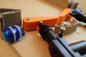
I recommend a cut-in-half ping pong ball. I know, All pictures here show another plastic-thing, but I did not have ping pong balls at hand originally.
Drive unit:
All 3D-models are available here:
https://www.printables.com/model/915546-simple-robot-car-wheel-drive-train-gearbox
Drive unit hints:
- The axle holes in my model are adapted to my 2.5mm axles and the quirks of my 3D-printer. For precise hole sizes, you might want to 3D-print a hole size template first, with the correct hole sizes in a flat piece that prints quickly. It should have:
- A hole that gives a good sliding fit for the axles (for the 2 bearings)
- A hole that is a press fit on the axles (for all gears)
- A hole that is a screw thread press fit (for the M4 wheel bolts)
- All additional parts can be seen on the "explosion" view left. The steel axles can be made from coat-hanger wire, but then you need to check what diameter yours is, and probably adapt the 3D-model accordingly (see last step)
- All holes in the base plate can be drilled 2.5mm, and the M3-screws can simply cut their own thread. Does not work with foam board, i guess :)
- The drive units can be used as drilling template so that the holes in the base plate are precisely where they need to be.
Electronics hints:
- I used green LEDs because they are very bright at 3V. The LEDs were SMD, which is why the LED/sensor assembly is a bit complicated.
- Technically any photo transistor should work. For photo resistors, some tests are needed.
- There is no sensitivity finetuning on the electronics side (yet). It is possible that the vehicle does not work because the sensor might be too sensitive. Bending the sensor units a bit away from the ground helps usually.
 joekutz

 Sepio
Sepio

 Colin Russell-Conway
 Chris Mitchell
I've worked on similar projects in the past and found that simple line-follower robots are great for teaching basic STEM concepts. It's amazing how something so straightforward can help students grasp logic, coding, and hardware integration. If you're looking for additional resources to dive deeper into STEM education or need help with writing reports on such projects, you might want to check out this essay paper writing services https://essaybox.org/ It can be helpful, especially for students who are balancing multiple assignments while working on hands-on projects. Overall, combining practical tasks like building robots with solid academic resources really enhances the learning experience!