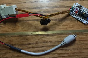
Using some analysis + hacking of the communication protocol used in the ClockWise Tools dial indicator, we create the possibility to digitally read the micrometer with less than $50 per tool.
Signal analysis using an AD2 reveals that the clock and signal lines, which can be accessed through a micro-usb interface, can be extracted from the D+ and D- lines respectively. The clock is shown to vary from dial gauge to dial gauge, but the signals all have the same format: once every ~40ms, we have a “burst” of a nibble. Six nibbles are communicated in this time frame, with a time division of ~1.58ms between each of these nibbles.
This communication protocol is designed such that the information of the absolute position can be read directly, in units mm, when translated into its binary equivalent. For my use case, the travel of the dial gauge was 0-0.5in (technically, 13943 state changes, resolution 1um -- a bit more than 0.5in). All six nibbles’ worth of data, converted into a binary number and decoded, gives us the state changes that are recorded by the micrometer. In “mm” mode, this translates directly to the micrometers that is read -- in “in” mode, it translates to the number of 5*10-5 inches that are read. For this particular micrometer, the “mm” mode has a slightly higher overall number of state changes, so it is the preferred usage method. The micrometer, however, has no method of distinguishing between positive and negative readings, so -100um readings appear as 100um. It is best used when zeroed to the maximum reach of the dial gauge (so non-negative values are read).
The key difference in communication protocols, which generally use the full scale binary representation of the data type to represent positive and neg. Numbers (e.g type “int” in C, being able to represent positive numbers and negative numbers through a division of 0-2^16-1, and henceforth, for the regular interpretation and the 2s complement), the communication protocol uses only the rising edge of the clock to communicate the readings -- for this particular dial gauge, negative readings and positive readings for the dial gauge state are both reported as positive numbers (e.g -50um readings → current state read by Arduino Nano = 50um).
One more problem that stood in the way was the operating voltage. ClockWise tools use 1.5V logic for their signals. Since no rectification devices work with 1.5V commonly, a simple MCP6004, with a gain bandwidth of 6MHz, and a rectification circuit created with a non-inverting amplifier circuit can help us jump this to 5V-0V logic range without errors from hysteresis or data losses.
 Tommy Liao
 ksk
ksk
 Kuldeep Singh Dhaka
 Sleepy Pony
 Bruce Land