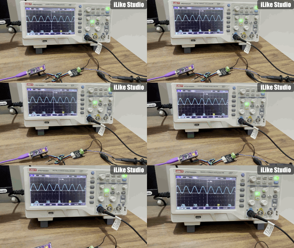
In the previous tutorial I had covered how PWM of Arduino can be utilised as DAC. Arduino Nano/Uno boards do not have any internal or onboard DAC units. But with serial, I2C or UART these microcontrollers can be interfaced with an external DAC unit. You would wonder why we need a DAC in a microcontroller, sometimes to get the processed data in audio or in continuous wave format out of a microcontroller we need this digital to analog conversion unit. Nowadays a lot of microcontrollers are working on ML and DSP structures, the best way to get the processed output is in the analog format so that it can be fed into any preamplifier or amplifier after the processing stage. In Digital signal processing(DSPs) all the processing is done on discrete data, on arrays of data. But in actual discrete it has no meaning. In the real world we can only understand a signal coming in analog form.

Digital structures are used in the microcontroller because it is easy to process the data digitally. With a simple mathematical equation coded in C++ or python can change the structure of data as per requirement. The string operations can be easily performed on a set of data, thus manipulating its values easily. There are some basic operations of time shifting and subtracting the value which can be easily performed on a discrete sampled data set. In this way ADCs and DACs are the fundamental need of a signal processing unit. This project is sponsored by PCBWAY. Get your custom PCB prototypes at an affordable price of $5 for 10 PCS from PCBWAY.
Components Required:

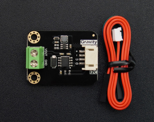
GP8211S DAC from DF robot
Arduino UNO
Python programmer
Arduino IDE
GP8211S 15 bit DAC units:
This is a 1-channel DAC module with I2C communication, a resolution of 15-bit, and an accuracy of 0.01%, capable of generating analog voltage outputs of 0-10V or 0-5V. The 0-10V or 0-5V voltage output is a standard driving method. It can be widely used in automation control scenarios such as lighting adjustment, frequency converters, valve regulation, and pump control, etc. This product can drive a variety of 0-10V or 0-5V controlled devices available in the market through Arduino programming.

The high precision and resolution of this module make it suitable for control scenarios that require higher signal accuracy, such as fine speed control or angle control.
DAC series modules are a range of products that can be controlled through I2C signals to generate voltage output signals. This series of DAC products not only offers a variety of output signal ranges, but also provides three selectable resolutions: 8-bit, 12-bit, and 15-bit. It allows for the choice of either single-channel or dual-channel configurations, and multiple modules can be cascaded to form a multi-channel output. This DAC modules have applications in:

Automatic light adjustment
Variable frequency drive (VFD)
Automatic valve regulation
Automatic water pump control
Specifications:
- Operating voltage: 3.3V to 5V
- Communication Method: I2C
- Chip Type: GP8211S
- Resolution: 15-bit
- Output Voltage: 0-5V or 0-10V
- Number of channels: 1 channels
- Value Range: 0 - 32767 corresponding to 0-5V or 0-10V
- Output voltage: 0.01>#/span###
- Output voltage linearity error: 0.01>#/span###
Interfacing with Arduino:

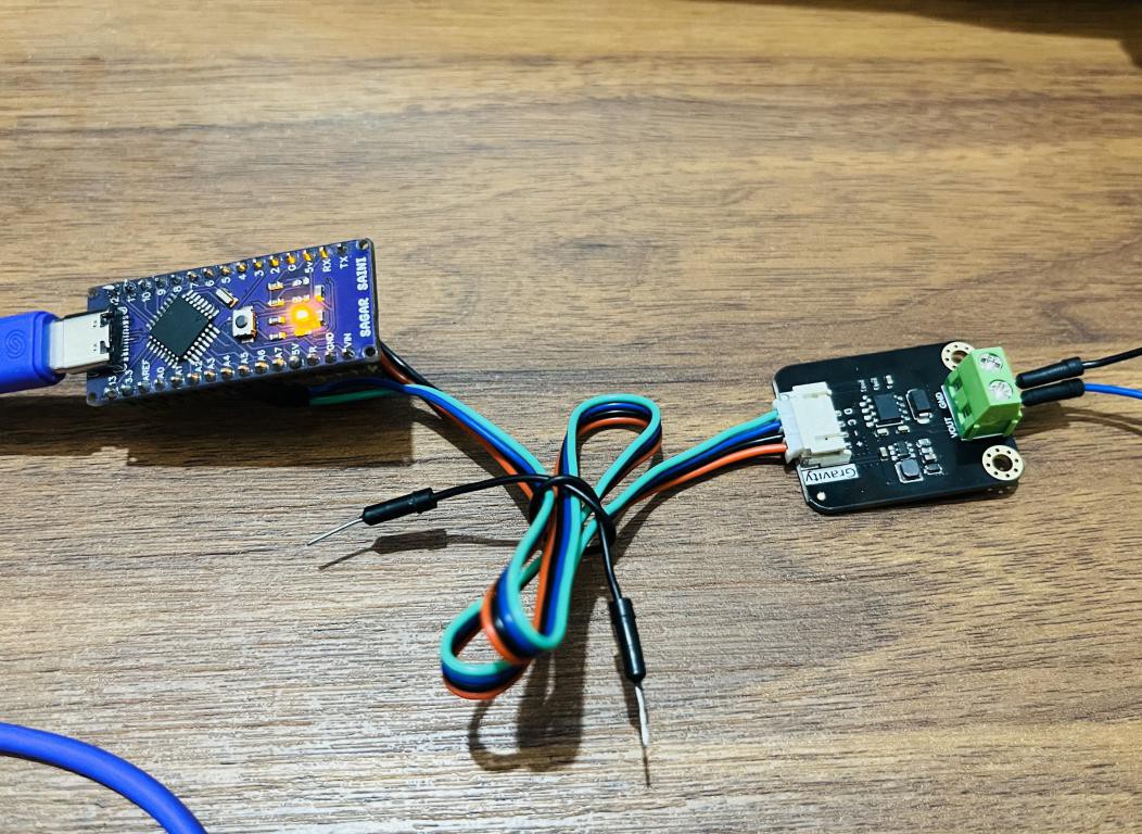
Here I have an I2C variant of this DAC module, Arduino I2C has a limited bandwidth and speed, that’s why a limited frequency signal can be generated using this module. To generate any waveform first we have to make an array according to the number of values DAC is going to cover with respect to time. These types of waves are easy to generate; a few examples are shown in the tutorial below. This array of values is known as a lookup table. Which is basically a list of numbers stacked up in a specified format such that values are taken one by one from that list and respective analog signals are generated.

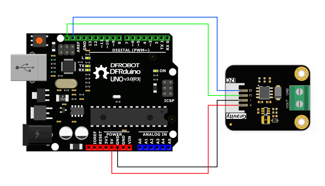
Connect the Arduino with the DAC module as shown in the figure above. Run the serial monitor, plot or get the output...
Read more » Lithium ION