TLDR:
- Design tools used:
- Fusion360, Plasticity, Blender, SolidWorks
- Material:
- PETG dyed green and amber
- Supplier:
Introduction
From the beginning we knew that the gunship needed a barrier shield; every good sci-fi ship needs a sick transparent shield that makes a satisfying "ding" when asteroids bounce off.
The 2023 swadge had a prototype that we called the "eggshell", a name inspired by the username of the 3D printing guru "eggman" who churned out 200pcs pre-event to give the squarewavebird a more ergonomic shape.
For 2024, we set our sights on bigger and better, moving away from the 3D printed pieces and embracing a more Professional™ manufacturing method: injection molding. MAGFest chose Protolabs as the supplier, as I had worked with them previously in my day job and was very happy with their user-friendly interface, web-based quoting and analysis tools, and turnaround time.
Design Process
The 3D design team consisted mostly of myself, Erik Jacobs, and Greg Lord.
1. Greg created some concept sketches that were used in other merch and swadge designs of a ship's hull. This formed the basis for not only the shell design, but the shape of the swadge itself.
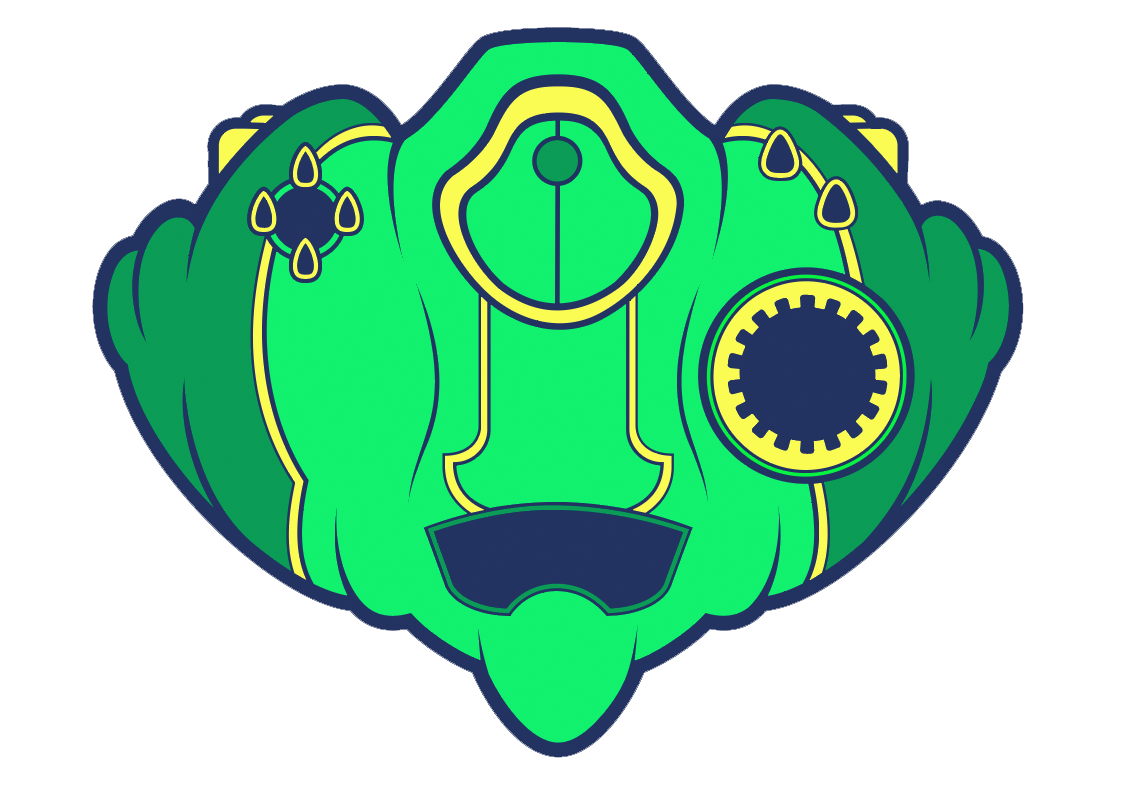
2. I exported a 3D STEP file and a 2D DXF from KiCad of the swadge PCB and components, and Erik pulled it into Fusion360.
3. Erik offset the PCB outline and created a base 3D model to prototype. Considerations were made for component clearances, ergonomics, and early Design for Manufacturing concerns - adding rounded edges, avoiding thin features, minding draft angles, and accounting for fastener interfaces. Erik noted the biggest challenge he had was the high poly count of the PCB geometry and translating that to Fusion360; in the end, he decided to fit a spline over the shape instead of rely on the exported outline to fit the PCB.

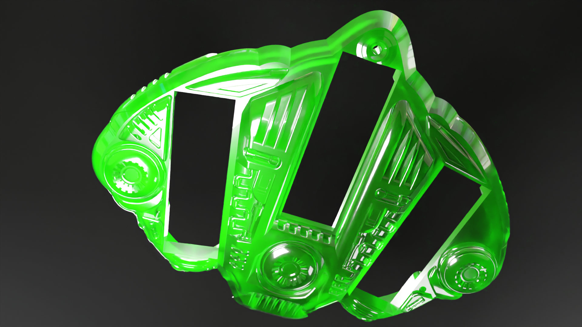
4. Erik passed the prototype 3D model to Greg, who created some really beautiful detailed models in Plasticity and Blender to bring the ship to life. The goal was to keep the functional footprint from Erik's model and to incorporate artistic features that brought it closer to the original sketches. Tubes, weapons, turbines, vanes, and more were added. The concept art was very detailed, shown rendered in Blender here:
5. I received the model at this point and needed to prep it for Injection Molding. Design for Manufacturing was my primary task at this point, as Erik and Greg had already accomplished the fit and form tasks. Injection molding is less forgiving than 3D printing, and requires many considerations for manufacturability. Protolabs has a really cool online interface that was able to clearly illustrate errors in the model that were adding cost or causing it to be not-moldable. Between that and the tools in SolidWorks to do some manufacturing analysis, we were very well-equipped to transition the concept to a manufacturable piece. Some considerations to be made were:
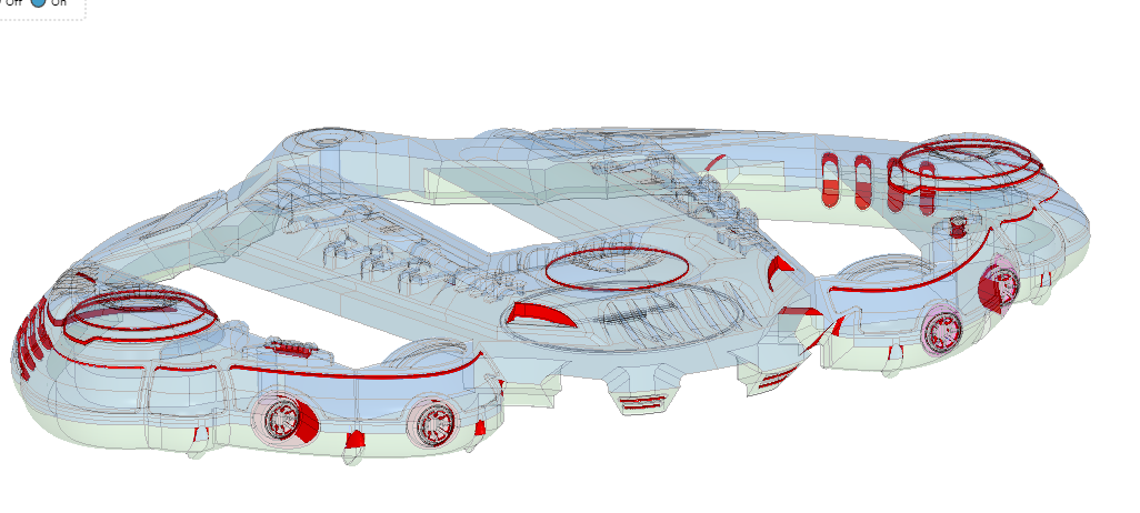
- Wall thickness - I needed to make sure the thickness of the shell was consistent or risk pitting, warping, or other errors in the final plastic. Here's a render from the Protolabs interface showing thick walls:
![]()
- Draft angle - as the piece is removed from the mold, it needs to have an angled wall in some areas to prevent it from basically suctioning to the mold. A 1-3 degree draft angle needed to be added on tall walls and sensitive areas. Red highlighted areas show where a draft was required:
![]()
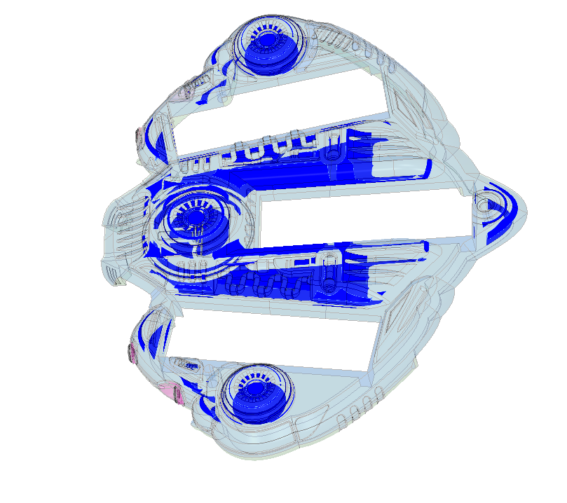
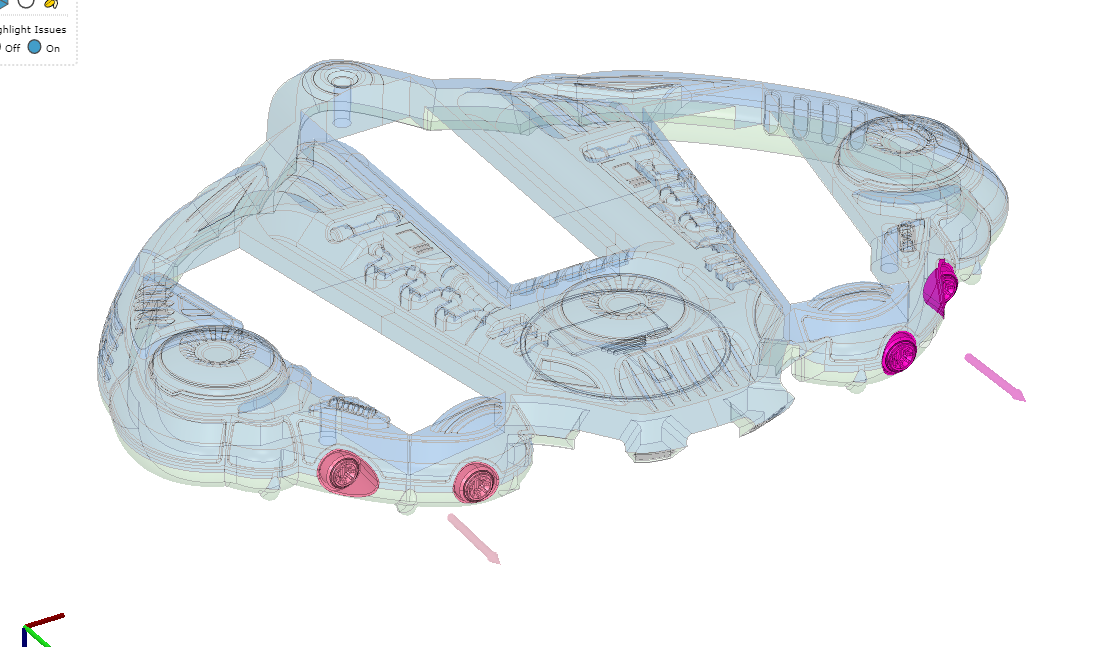
- Overhangs and undercuts - overhangs can be molded, but for an extra cost because they require what are called "side actions", or a removable part of the mold which ejects from the side. We had like $6 to work with, so I needed to adjust the model to remove the undercuts. Here's an image showing the model with side pulls required:
![]()
- Material selection - we really wanted a transparent shell, and I selected PETG because I loved the green and amber colors which would fit really well with the purple and red PCBs of the gunship.
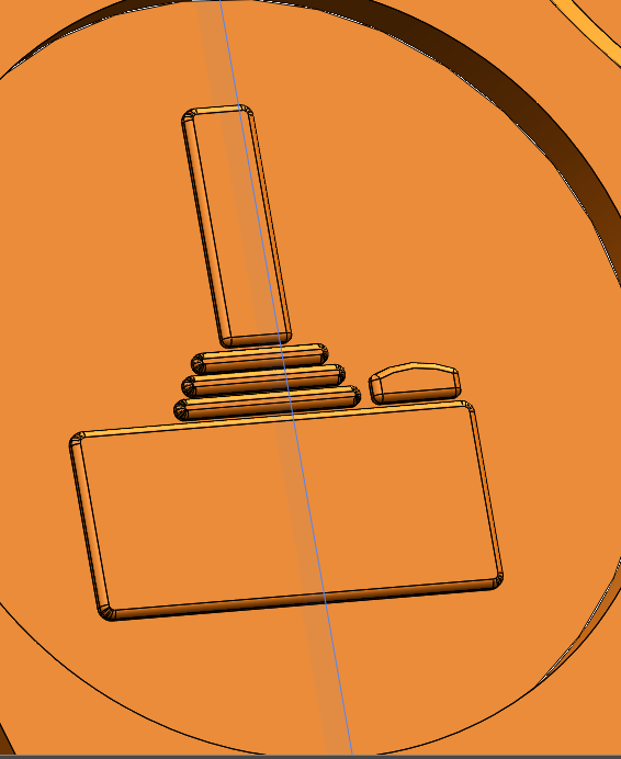
- Embossing vs Engraving - Embossing details in the final plastic is preferred to engraving. This is due to a couple of things, but primarily because you have to remove less material when machining the mold, which reduces cost. Additionally, raised letters/details on a part are easier to read, and recessed text in a mold allows for polishing, whereas raised letters in a mold make it difficult to achieve a good finish. I embossed the MAGFest logo into the shell:
![]()
We were assigned a representative to sit with and resolve these concerns, and once the model was ready to go we kicked off manufacturing. 6 weeks later, just a bit after Christmas day, the shells arrived at the warehouse. Great success!
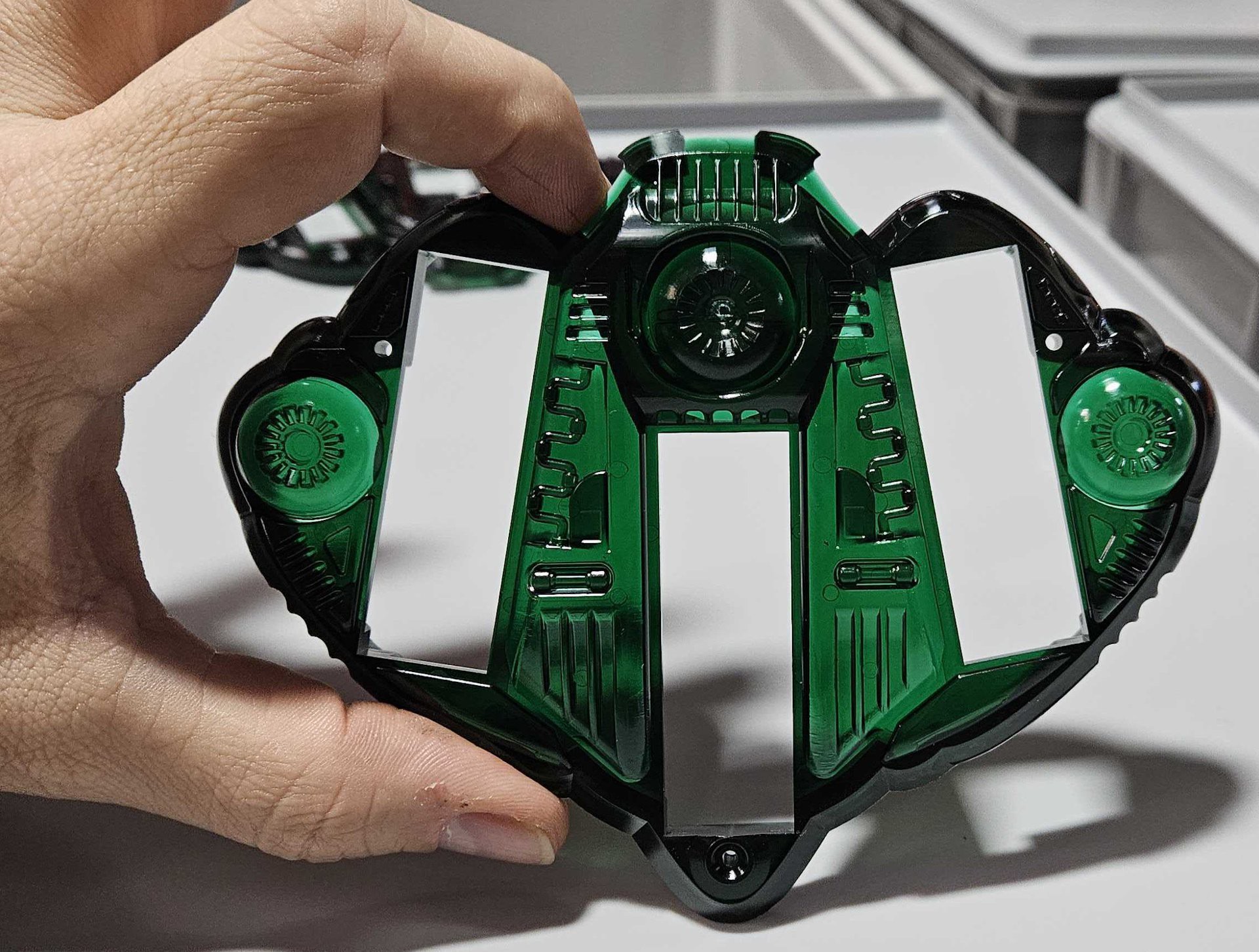
In the end, we ordered 1500 barrier shells and they look SICK.
Lessons Learned
No project is perfect and we learned a lot along the way. Some of the things the team noted were:
- Starting DFM earlier in the process; Greg learned a ton along the way about injection molding, and he noted that he made some "rookie mistakes" with very detailed models that ended up not making it to production.
- Personally I would have budgeted more time; we kicked off the design at the beginning of October, and I think we would have benefitted from starting at the beginning of September instead.
A sidenote: we are currently working on the 2025 swadge shell, and it's the middle of October, so while I learned my lesson clearly I didn't implement changes. To Erik's credit, he already has models, but we are basically following the same timeline as we did for the barrier shell, lol oops
- I was unhappy with how dark the green was in some areas; the plastic was far too thick. If we do a transparent shell again, I am going to be more mindful of wall thickness.
![]()
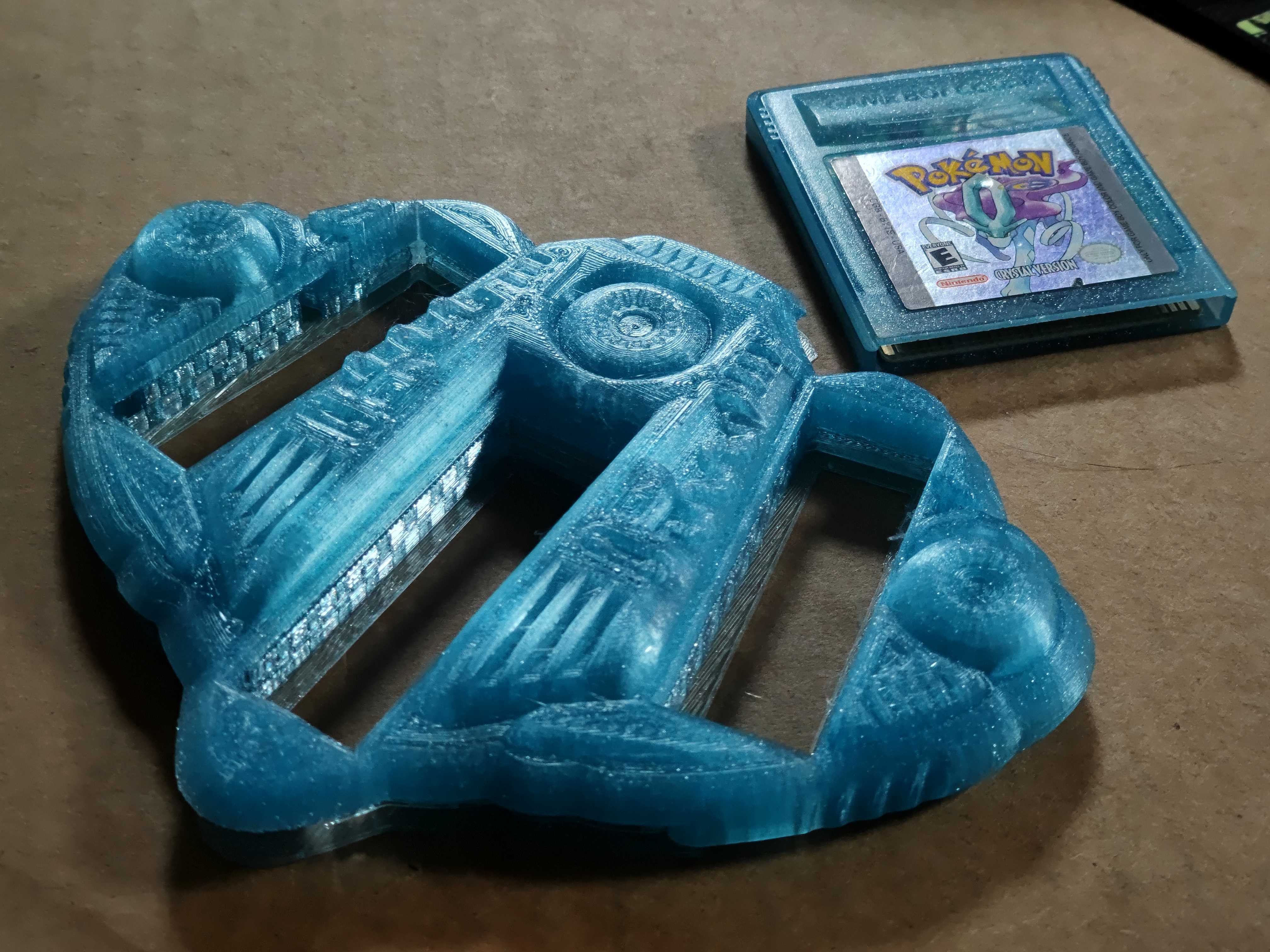
- This design was very manufacturing-method dependent; it prints "okay" on FDM printers, though I love my Pokemon Crystal themed shell Erik made for me:
 Emily Anthony
Discussions
Become a Hackaday.io Member
Create an account to leave a comment. Already have an account? Log In.