I've spent the last few weeks designing a new gear train for the rollers.
Prototype 1 used a small motor with built in gearbox :
| 37-1216 | RVFM Right Angled Motor and Gearbox 1:220 | £1.64 |
This was mounted through the rear base part with the motor protruding into the gap between the front and rear base parts. The gearbox output at the back was attached to one gear meshing with another gear driving the roller. Incidentally the second gear also had vanes which could block the photodetector, allowing the circuit to measure rotations.
Taking apart the gearbox showed 4 plastic gears, with maybe 4:1 ratio each (4*4*4*4=256). These gear teeth are tiny, perhaps 0.25mm which are too small to accurately 3d print. Also the gearbox is large (20x30x10mm) so would be good to remove it if I can replace the mechanism myself.
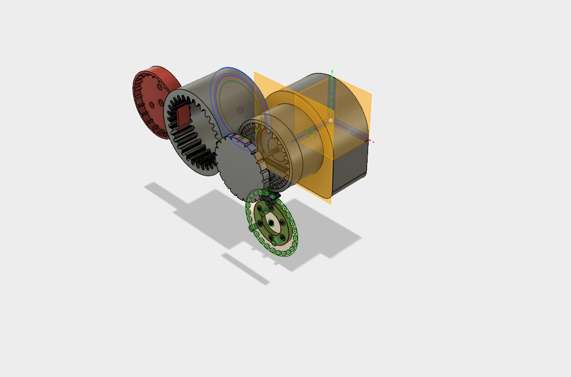
Also even the 220:1 gear ratio left a rotational speed of about 1 rev/sec, too fast. I need another factor of 5 slower, around 1000:1. Googling tells me there are two gearing mechanisms that might help : planetary gear sets, and epicyclic gears. In fact I think I'm going to use both : planetary gears to provide an initial 5:1, then another 400:1 from a linked pair of epicyclic gears. And all this from only a few pieces : the raw motor with gear, driving three planetary gears, within 1 ring gear cut into the case, the planetary carrier attached to a cam, which rotates a joined pair of epicyclic gears, one rotating against the case, and the other side rotating againt a ring gear attached to the first roller.
Picture from Fusion 360 here!

Inspired by Oskar van Deventer's Extreme Reduction:
Electronics will control the speed or the duty cycle of the motor to drive the minute disc.
A second epicyclic gear drives the hour disc at a 12:1 ratio. Voila!
 terryspitz
Discussions
Become a Hackaday.io Member
Create an account to leave a comment. Already have an account? Log In.