I finally received my custom boards from OSBPark, and I got some fresh solder paste in the mail so I was able to begin soldering Hirose connectors to pads. This was probably a poor choice of component for my first forays into SMD soldering, as the feet of the Hirose connector are super fine pieces of metal. I used a jumper lead to gently brush paste onto the copper pads, placed the connector, and then heated it with my heat gun until it melted. Of course, I had some bridged connections, but I fixed them with my soldering iron set to 350 by poking at the bridges until they resolved. It seems to have worked alright, though I did lose pin 38 out of the connector. Luckily that pin is not connected to anything, so could be worse.
During this process, I realized that I have no idea how to tell if any of this is done right. As in, how am I supposed to know this keyboard works when I'm not entirely sure how to get it to talk to a microprocessor? How could I ever tell if the issue was related to the board or to the firmware I loaded onto the microprocessor? To confirm my keyboard connector worked, I needed to devise a non-MCU driven way to check that all the connections are sound and that the keyboard is producing the correct signal when a key is pressed.
I investigated how keyboards are designed. Generally, they have a row and column configuration, and an MCU will "scan" the keyboard by placing HIGH across the column inputs. Each column would see this HIGH signal once per scan, and the MCU would "listen" at the row outputs for a signal. As a MCU controlling a keyboard has a clock cycle in the order of 10s of MHz, that means the keyboard MCU is scanning each column for row inputs every 100 nanoseconds or so.
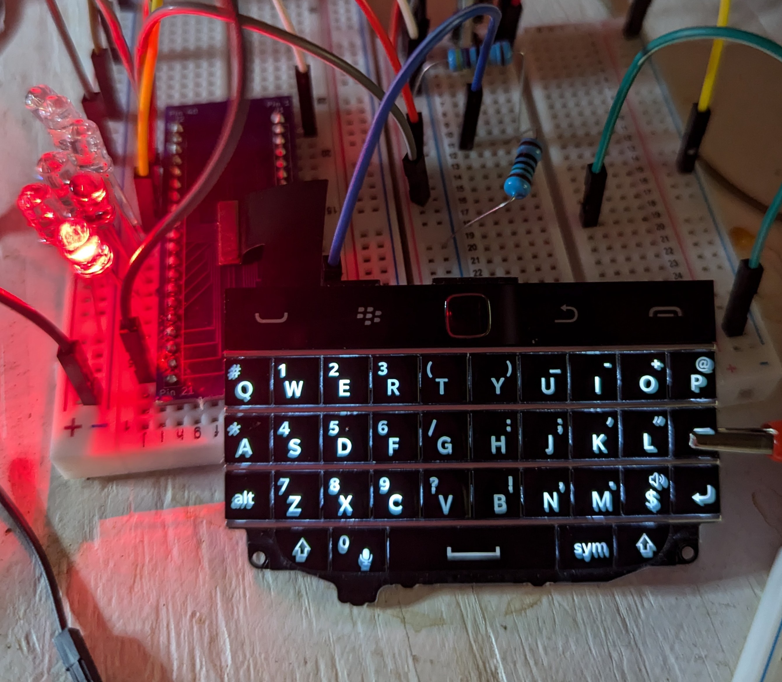
Learning this, I devised this plan: put ~1.8 V on each COL pin on the keyboard (pins 12-18) and add an LED from each ROW pin (26-32) to ground. Thus, as all columns are now powered as if they were being scanned, when I press a key the corresponding LED will report which row is being connected to the power from a column. Using this initial setup, I could map key/row relationships easily, which I recorded into a spreadsheet. Then, I removed power from each column, one at a time, and checked which keys were disabled, which would mean that they were powered by the column I had disconnected.

Only COL5 and the LED backlight is powered in this photo, and a clip is pressing the BKSP key to demonstrate the LED mapping of the keyboard.
This worked very well, and I was able to quickly map this keyboard. I did note 7 keys that did not power an LED ever when pressed, and I also noted that no key appeared to need COL7 powered to output signal. While at first glance this may suggest that we simply have a broken COL7 input (either keyboard or connector), the keys aren't exactly in the most reasonable place for a final keyboard column. Additionally, I also got the keyboard backlight to work, but it seems like some of the LED backlights are not lighting up.
The weird backlight and the key issues mean I very well could just have a broken Q20 keyboard. I did buy it on AliExpress, and there's some junk on the back of the board that suggests it could've been pulled from a BBQ20 unit, so only the gods know what happened to this component before it arrived. I thus decided to buy five of the things: if all of them malfunction in the same way, that means I've got a botched connection. If they behave properly, it means that first keyboard is simply broken, probably by a previous owner.
 janusprotocol
Discussions
Become a Hackaday.io Member
Create an account to leave a comment. Already have an account? Log In.