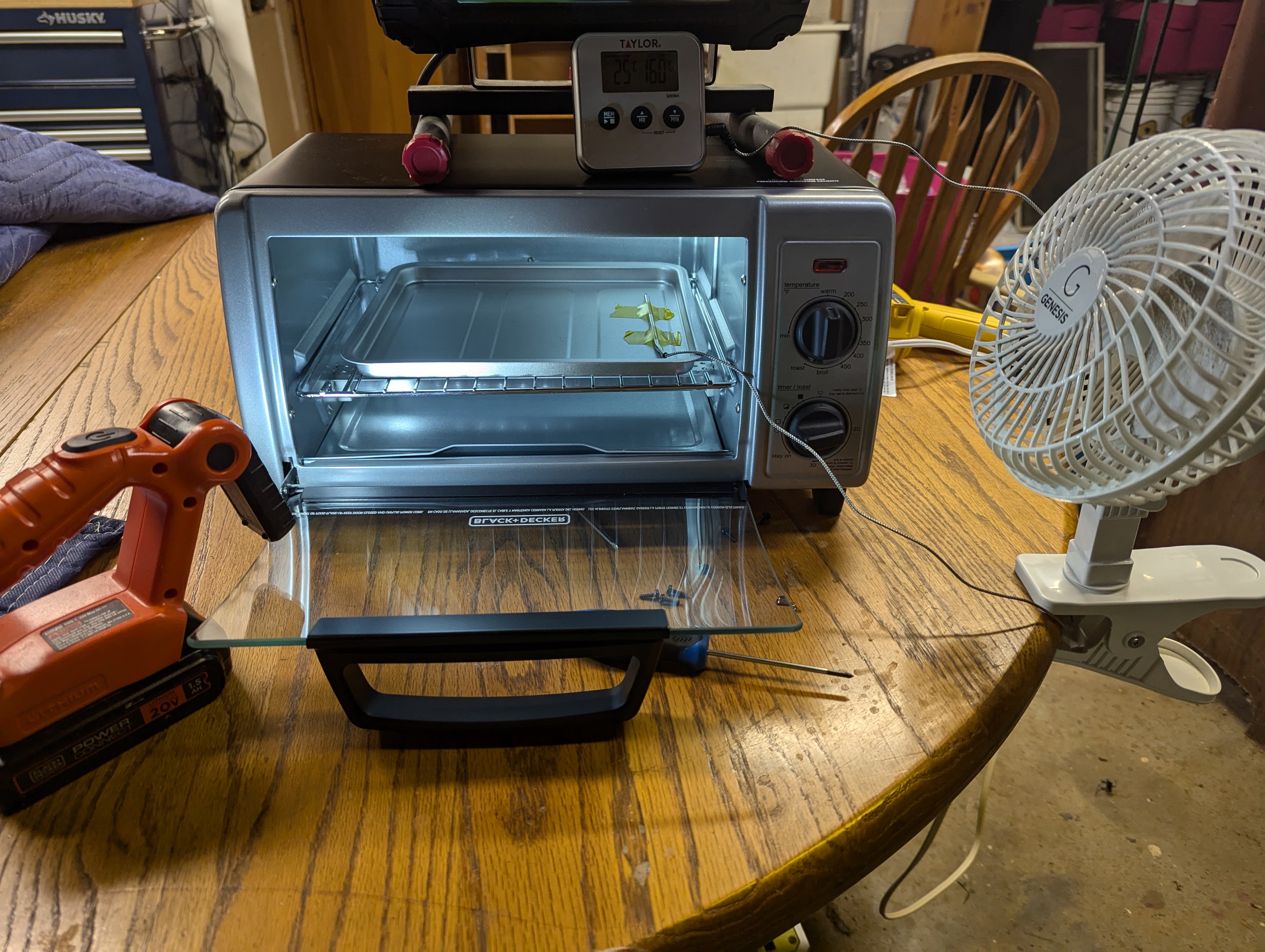
While I waited for PCBWay to produce my boards and the accompanying stencil, I contemplated how I was gonna put this board together. I ordered a smaller, more controllable hot air gun, but as I got it from AliExpress it's unknown when things will arrive. I had read stories online about people hacking a toaster oven (AKA making an Easy Hack Oven) to act as a reflow oven, which was intriguing. After researching desired characteristics and what was available locally, I found a Black & Decker quartz element oven with power rating > 1000 W and reasonable price at Kroger, and I purchased a Walmart oven thermometer with probe. While my first thoughts were to go full send on hacking this thing, but as I thought more and more it seemed like I could just...watch the oven and control it manually for these IB backpack boards. So, I taped the probe to the oven tray, did some empty tests to get ramp rates and temp overshoot characteristics, and tested my planned procedure with solder paste only on the board.

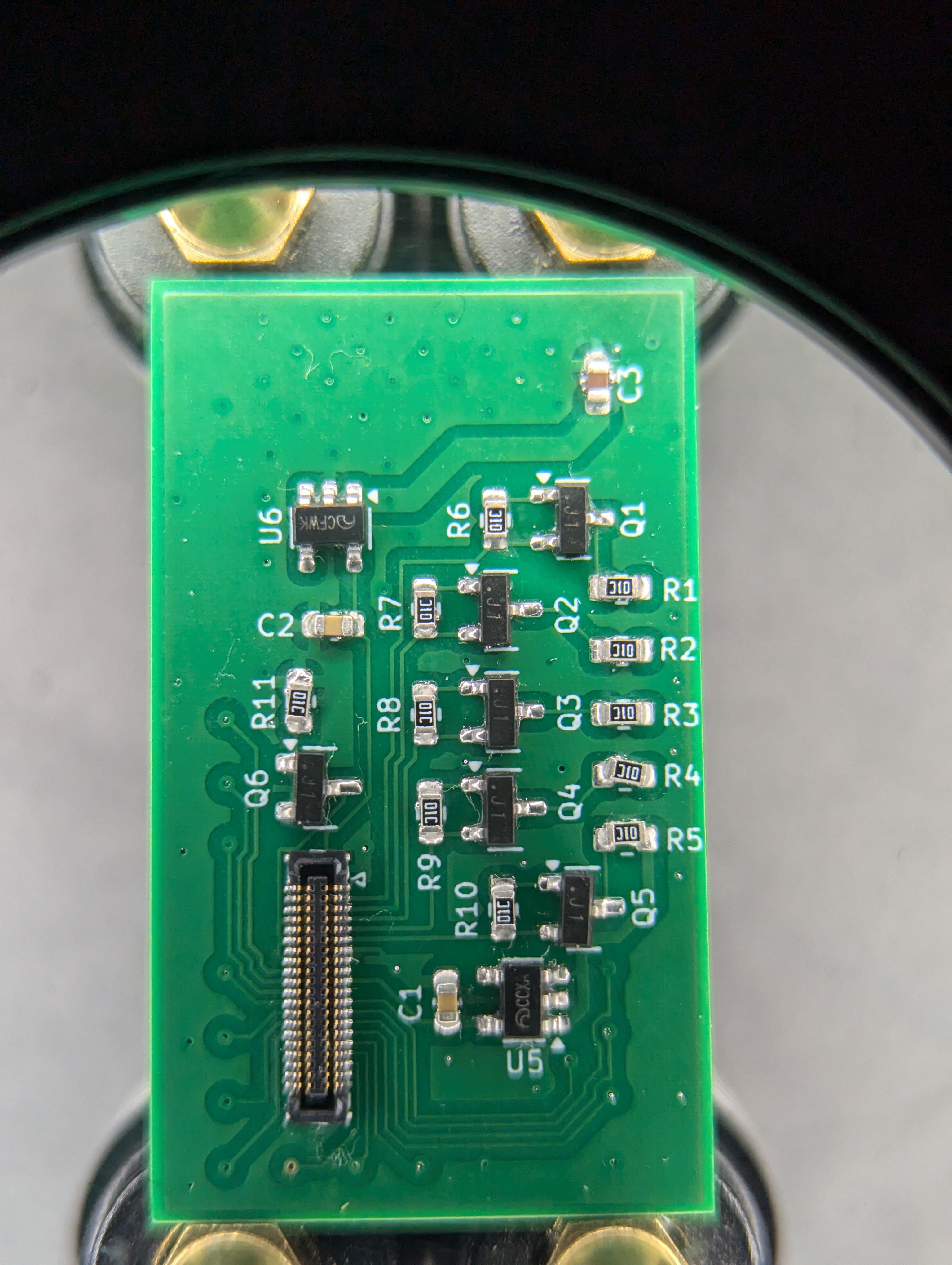
That went well, so I applied paste with the stencil, placed components, and ran the reflow procedure. I did place kaptom tape on some of the in-pad vias, as I wasn't paying hundreds of dollars for PCBWay to fill them with resin. The hope for this was the tape would keep any molten solder from the pad from running out from under the board, which is why people fill vias in the first place when they're in pads. Anyway, during reflow I cut the oven power at 110 C, which cruised slowly over a minute or two to 155 C or so, then pulled the tray out an applied cool air via a handheld fan until the temperature dropped to 120 C. At that point I removed the board from the tray and placed it on my helping hands platform to rapidly cool.


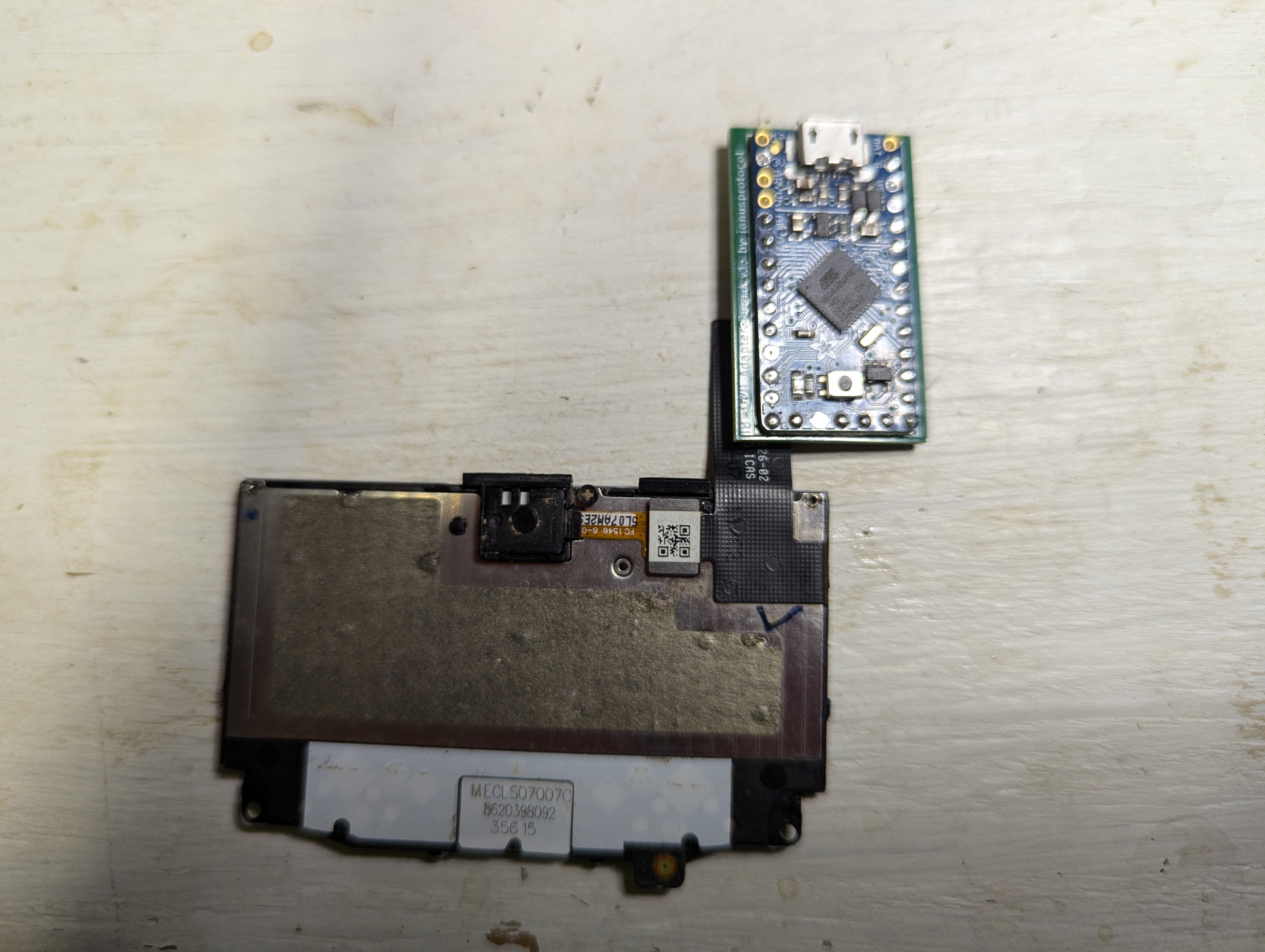
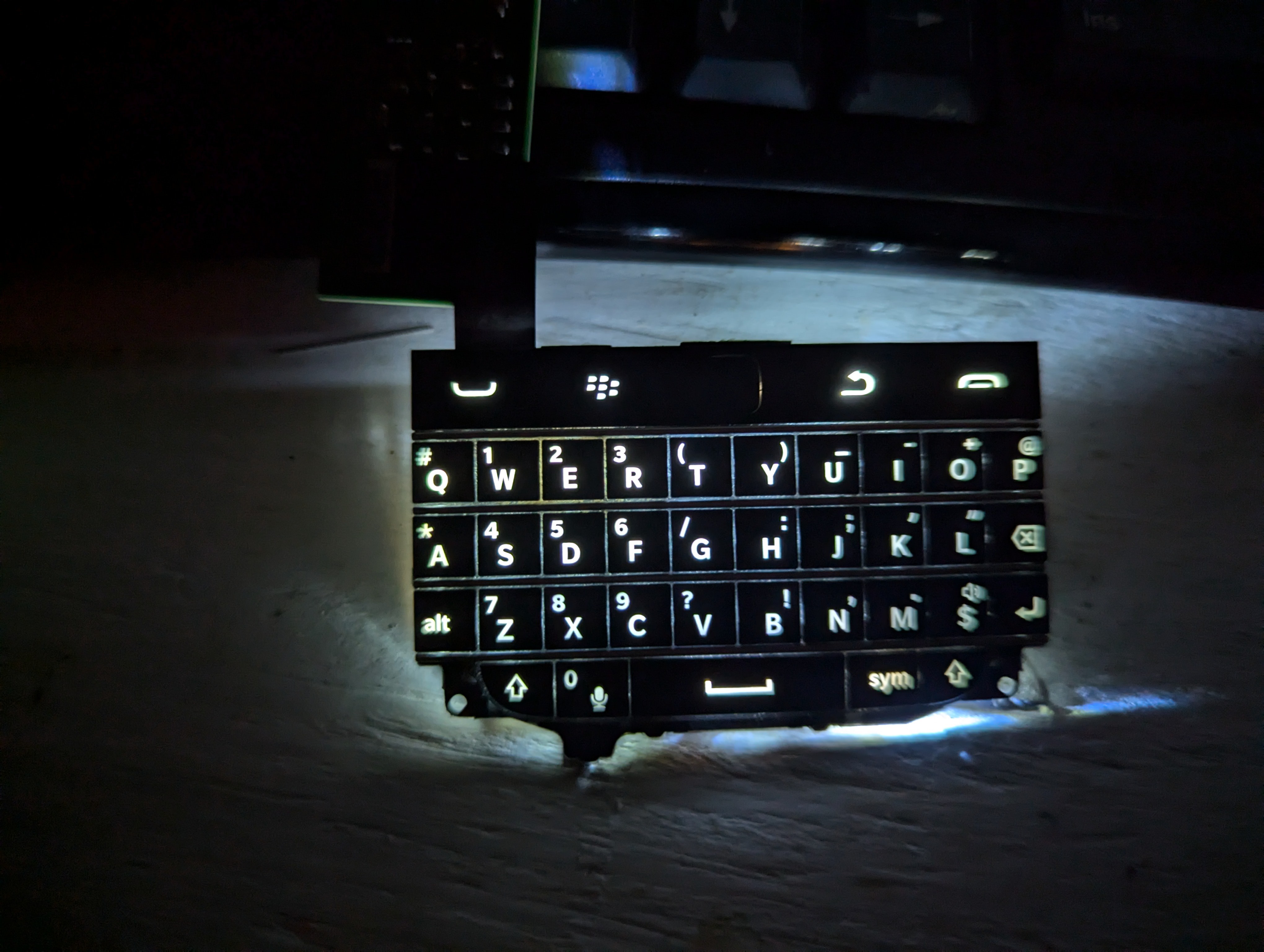
The only flaws noticed were the C3 capacitor falling off almost immediately, R5 was comically skewed off of one of its pads, and the Hirose connector had a single solder bridge across pins 4 and 5. I resoldered C3 and R5, then resolved the bridge with some flux and a poke from my soldering iron. While I don't have any firmware ready to drive the keyboard, I can easily program the board via Arduino IDE to control the brightness of the backlight via PWM output from the IB 32U4 Pin 5. It looks SO much better than my initial test, which is super encouraging.

I guess now I need to buckle down and figure out if I can use QMK or some other existing keyboard firmware package to drive the keyboard or write my own. I'm closer to the end of this phase of the project than the beginning, and once complete I have to test some display in a similar manner. I'll probably start designing the motherboard for the HB1 at that point as well, since my experience with the IB 324U really demonstrated the power of these prefabbed boards to expedite prototyping.
 janusprotocol
Discussions
Become a Hackaday.io Member
Create an account to leave a comment. Already have an account? Log In.