How does a Single Channel Relay work?
A relay is an electrically operated switch that uses an electromagnet to mechanically operate a switch. When an electric current passes through the coil, it generates a magnetic field that attracts a lever and changes the switch contacts. The relay can switch between the normally open (NO) and normally closed (NC) contacts.
When the relay receives a signal from the Arduino, it activates the electromagnet, closing the circuit between the common (COM) and normally open (NO) terminals, thereby allowing current to flow through and power the connected device, such as a fan. When the signal is turned off, the relay deactivates, breaking the circuit and stopping the current flow.
Specification
- Digital output controllable
- Compatible with any 5V microcontroller such as Arduino.
- Rated through-current: 10A (NO) 5A (NC)
- Control signal: TTL level
- switching voltage 250VAC/30VDC
- switching current 10A
- Size: 43mm x 17mm x 17mm
Single Channel Relay Module Pinout

The single channel relay module typically has the following pins:
- VCC: Connects to the 5V supply from the Arduino.
- GND: Connects to the ground.
- IN: Receives the control signal from the Arduino to switch the relay.
- COM (Common): Common terminal for the relay.
- NO (Normally Open): Connected to the common terminal when the relay is activated.
- NC (Normally Closed): Connected to the common terminal when the relay is not activated.
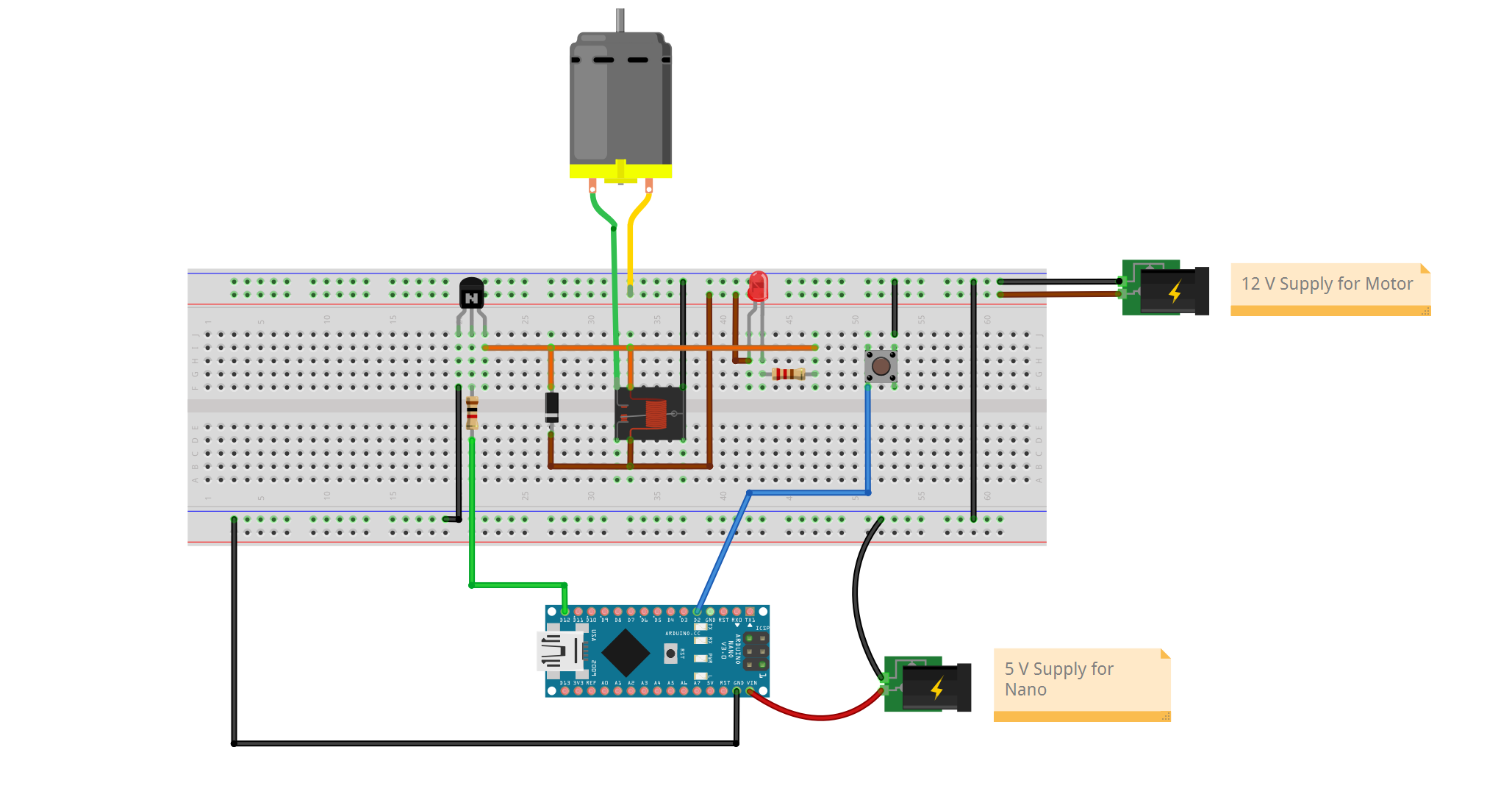
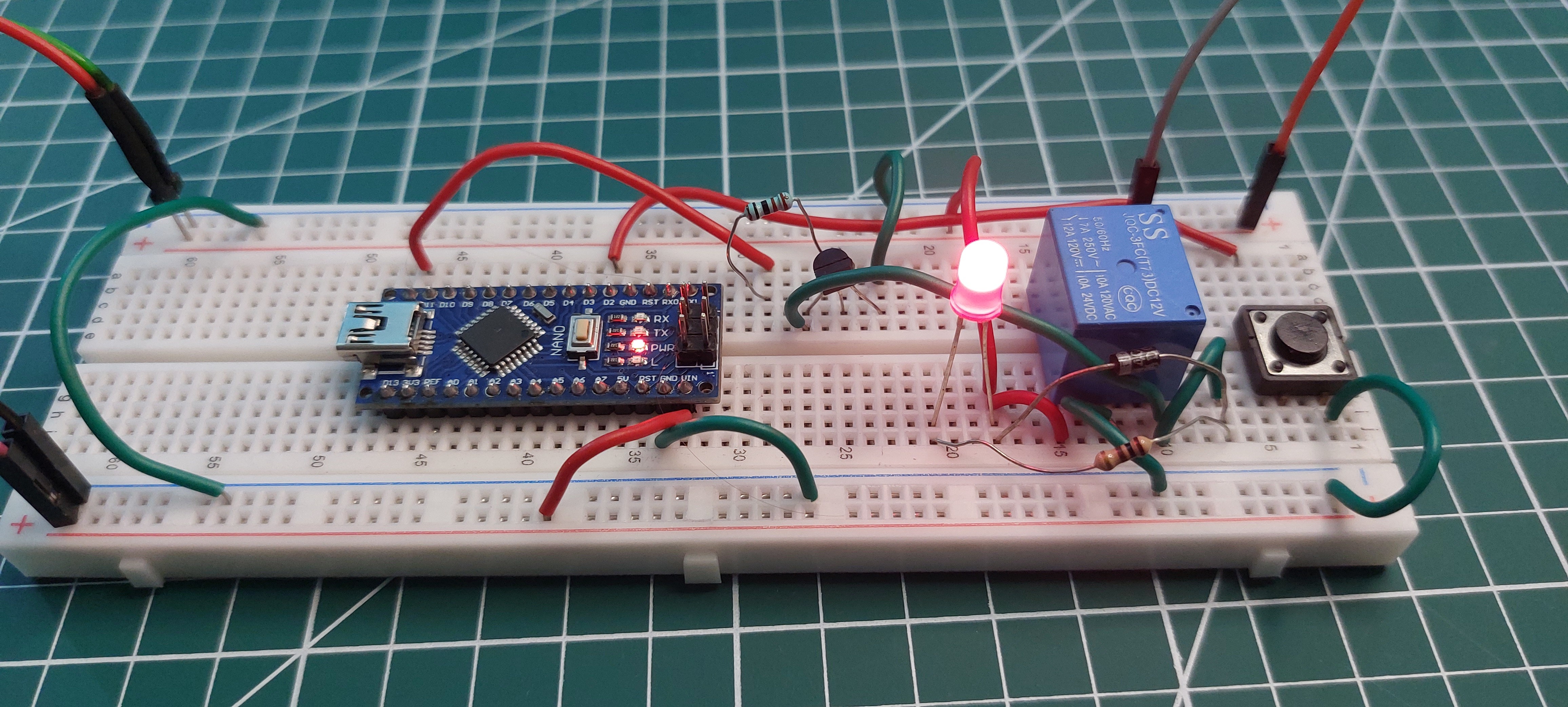
Circuit Diagram of Interfacing Single Channel Relay with Arduino Nano

Wiring Connections:
Arduino Nano:
- GND: Connected to the ground rail of the breadboard.
- 5V: Connected to the 5V power rail of the breadboard.
- D2 (Digital Pin 2): Connected to one terminal of a push button switch.
- D12 (Digital Pin 12): Connected to the base of the NPN transistor through a current-limiting resistor.
Relay Module:
IN: Connected to the collector of the NPN transistor.
GND: Connected to the ground rail of the breadboard.
VCC: Connected to the 5V power rail of the breadboard.
NPN Transistor:
Collector: Connected to the relay module's IN pin.
Base: Connected to the Arduino Nano's D3 pin through a current-limiting resistor.
Emitter: Connected to the ground rail of the breadboard.
DC Motor:
Negative Terminal: Connected to the ground rail of the breadboard.
Positive Terminal: Connected to the normally open (NO) terminal of the relay.
Power Supplies:
5V Supply for Nano: Positive terminal connected to the 5V power rail of the breadboard. Negative terminal connected to the ground rail of the breadboard.
12V Supply for Motor: Positive terminal connected to the common (COM) terminal of the relay. Negative terminal connected to the ground rail of the breadboard.
Push Button:
One terminal connected to the ground rail of the breadboard.
The other terminal connected to Arduino Nano's D2 pin.

Circuit Working
The Arduino Nano is powered by a 5V supply, while the motor is powered by a separate 12V supply. A push button connected to digital pin D2 of the Arduino is used to trigger the motor. When the button is pressed, it pulls pin D2 to ground, signaling the Arduino to send a high signal to pin D12. This high signal activates the NPN transistor by making its base-emitter junction forward-biased, allowing current to flow from the collector to the emitter. The collector of the transistor is connected to the relay module's input pin (IN), and when the transistor conducts, it energizes the relay. The relay then closes its normally open (NO) contact, connecting the 12V power supply to the motor, which starts running. When the button is released, the signal at D12 goes low, turning off the transistor and deactivating the relay, which stops the motor. This setup effectively uses the Arduino to control the motor's operation through the relay, with the transistor serving as a switch to handle the relay's activation current.
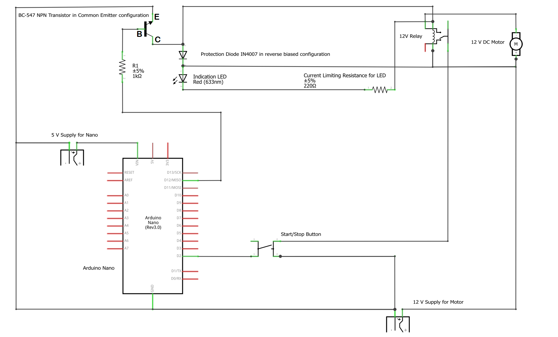
Here is the schematic diagram:

If you want to learn how to interface 5V 4-Channel Relay Module with Arduino checkout: https://playwithcircuit.com/interfacing-5v-4-channel-relay-module-with-arduino/
Arduino Code
#define RELAY_ON  1
#define RELAY_OFF 0

#define Relay_PIN   12
#define Button_PIN  2

int relay_pin_state = RELAY_OFF;

// Inline function to check if button is pressed packed with debouncing logic
inline bool chkButtonState(int pinNum, int checkState, int debounceDelay) {
  if (((digitalRead(pinNum) == checkState) ? true : false) == true) {
    delay(debounceDelay);
    return (((digitalRead(pinNum) == checkState) ? true : false) == true);
  } else {
    return false;
  }
}

void setup()
{
  // set the relay pin as output
  pinMode(Relay_PIN, OUTPUT);
  // set the button pin as input
  pinMode(Button_PIN,INPUT_PULLUP);
  // Initially Turn Off the Motor
  digitalWrite(Relay_PIN, RELAY_OFF);
  relay_pin_state = RELAY_OFF;
}

void loop()
{
  // check if button is pressed or not with 20 ms debounce delay
  int ButtonState = chkButtonState(Button_PIN, LOW, 20);

  // Toggle relay state on button press event
  if(ButtonState){
    relay_pin_state = ~relay_pin_state;
    digitalWrite(Relay_PIN, relay_pin_state);
    delay(300);
  }
}
 Akshay Jain