 Tobias
So, while the procrastinator in me was happy to have a USB cable running up the wall, the perfectionist in me could only stand that for a couple of weeks. Thankfully it's fairly easy to run a cable through my walls, and at first I had a 4 meter cable running to a 5 volt power supply. Of course, it didn't take long to find out just how much resistance there is in 22AWG cable at low voltage.
The plan was always to switch to PoE, and in my inveterate browsing of Aliexpress, I came across the RT9400/RT9460 PoE module. The official RPi PoE module might be a better option, but the RT9460 has the advantage of fitting into my tight space constraints, and it's nice that it's a fair bit cheaper. I've also seen people using the common DC-DC modules to power a Raspberry Pi, and at the end of the day this really is just a DC-DC converter. It does, however, have an isolation transformer, and it's designed to operate at 48V, which I think is on the high end for most of the cheap DC-DC converter modules.
The real problem is that there isn't any good information on how to use it to power a Raspberry Pi. Adafruit sell a PoE module with a different part number, but which looks the same and has the same pinout, but I had absolutely no luck trying their suggested wiring.
So, with all of that said, I'll show you how I wired a RT9460 PoE module to supply power to my Raspberry Pi. But first, an important note: I'm using a RPi 4, and I can't tell you if these instructions will also work for an RPi 3, 5, or anything else (oh, and in case it needs saying, I can't guarantee that if you try this you won't set fire to your RPi, workbench, ethernet cable, fingers, house, or anything else - playing with cheap Aliexpress electronics can be a dangerous game).
First we must ask... what is the PoE connector? Essentially it's a direct connection to the ethernet pins in the RJ45 jack. More accurately, it's a direct connection to the centre taps of the coupling transformers for each ethernet pair, which is good, cause that's what we need to the power from the power over ethernet.
So now we just need to work out which pins are which on the Raspberry Pi 4 PoE header. A quick bit of poking with a multimeter let me work out which PoE header pin corresponded to which ethernet pins:
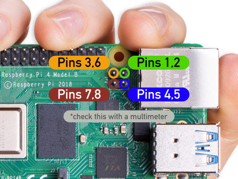
My PoE switch provides +48V DC on pins 4&5, and negative on pins 7&8, which according to wikipedia is Mode B PoE. A bit more poking with the multimeter (watch out for arcs at this voltage!) confirms the pinout which, is nice.
Now we just need to hook up the RT9460 PoE module, but here we run into the next challenge. The data sheet for the RT9460 is clear about which ethernet pin needs to be connected to which RT9460 pin, but then provides wiring diagrams for 100M and 1000M ethernet that have conflicting wiring. Specifically, the data sheet says for 100M, VA1 and VA2 of the RT9460 should be connected to ethernet pins 1,2 respectively. for 1000M, VA1 and VA2 of the RT9460 should be connected to ethernet pins 7,8 and 4,5. So which should we use?
At this point it's probably worth noting that I don't have any idea how PoE works, and I'm just prodding things until they work. But, according to the data sheet, the RT9460 is not polarity sensitive, in getting this to work I tried just about every combination, and the module didn't fry...
So, at last we get to the good stuff, an actual wiring guide. Here's what worked:
- RPi PoE header (ethernet pin 4,5) - to - RT9460 VA1 (pin 1)
- RPi PoE header (ethernet pin 7,8) - to - RT9460 VA2 (pin 2)
- RPi PoE header (ethernet pin 1,2) - to - RT9460 VB1 (pin 3)
- RPi PoE header (ethernet pin 3,6) - to - RT9460 VB2 (pin 4)
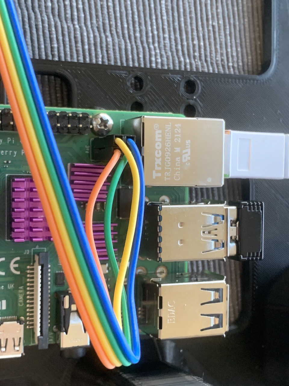
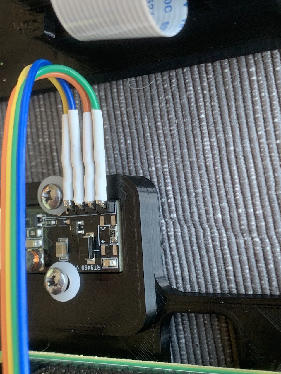
And here's what it looks like in practice. Important not, the color of these wires means nothing - I soldered them on before I double checked the pins (sigh):
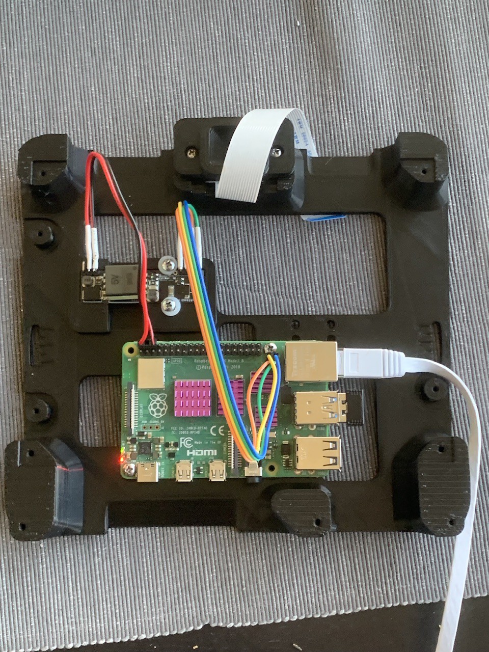
And here's the overall view:
Thanks for coming along on this alarmingly long journey, and leave you with some last notes:
- breadboard hookup jumper wires worked great for the 48V input into the PoE, but got alarmingly warm when I tried to use them on the 5V output - the current at 5V is way too high for these jumpers, so solder up something else
- According to wikipedia: "The PSE [the Power Sourcing Equipment i.e. the PoE switch or injector], not the PD [the Powered Device], decides whether power mode A or B shall be used. PDs that implement only mode A or mode B are disallowed by the standard". This would seem to mean that the RT9460 isn't compliant with the PoE standard. I don't really know if this will work with any other PoE power supply.
- As you might of guessed, the sum total of my experience with PoE has come from wikipedia and my multimeter, so proceed with caution. If you think I've made any mistakes, please don't be shy of saying so in the comments, so we can all learn together!
Discussions
Become a Hackaday.io Member
Create an account to leave a comment. Already have an account? Log In.