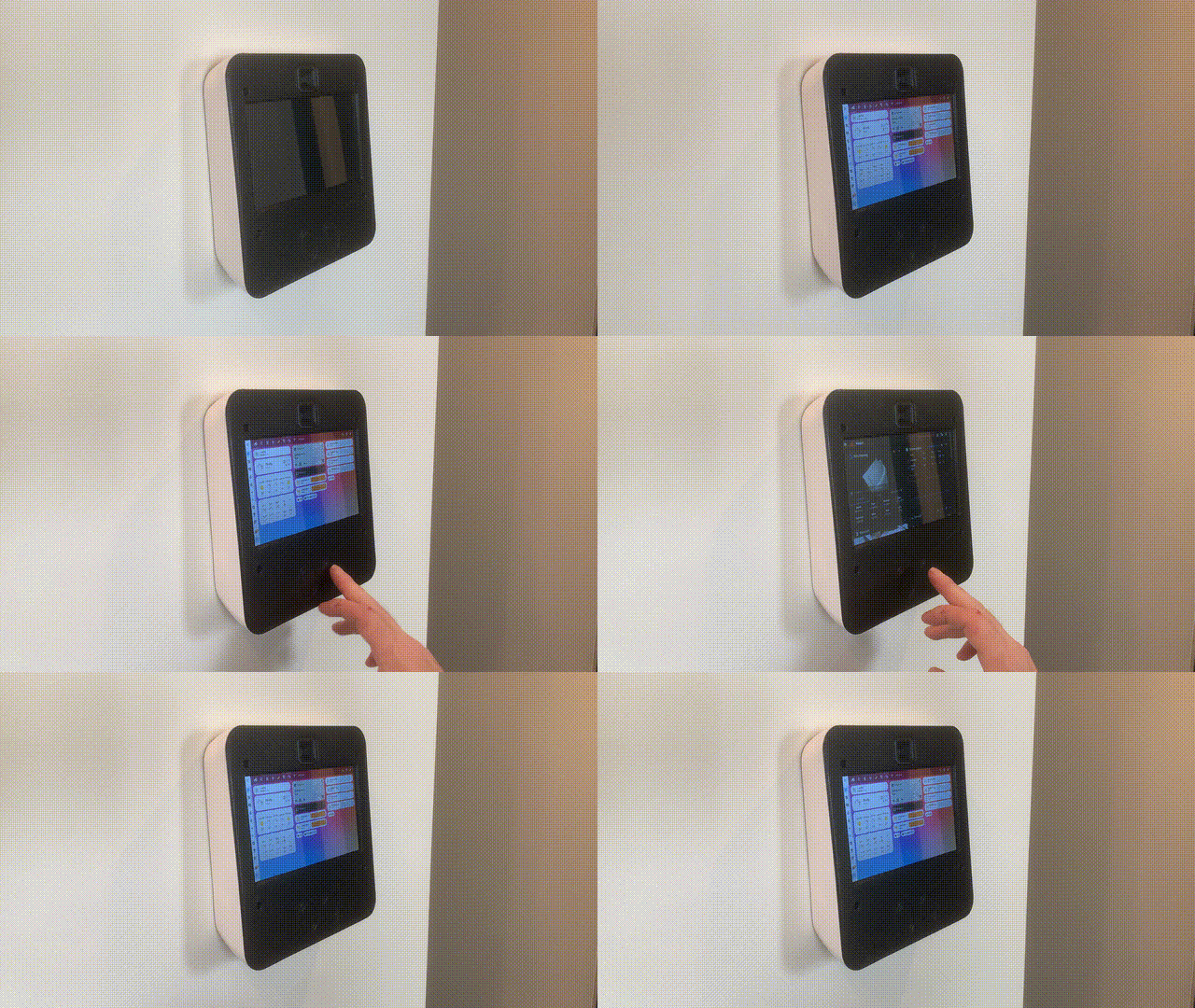
After leaving the front panel buttons unimplemented for a while, a really helpful comment from @ryan-worrell got me thinking about how they could be set up. The way I decided to go was to use the buttons to switch back and forth between a few different browser-based apps. In my case this was Homeassistant, and Klipper for my 3D printer. Here's what it looks like in action:

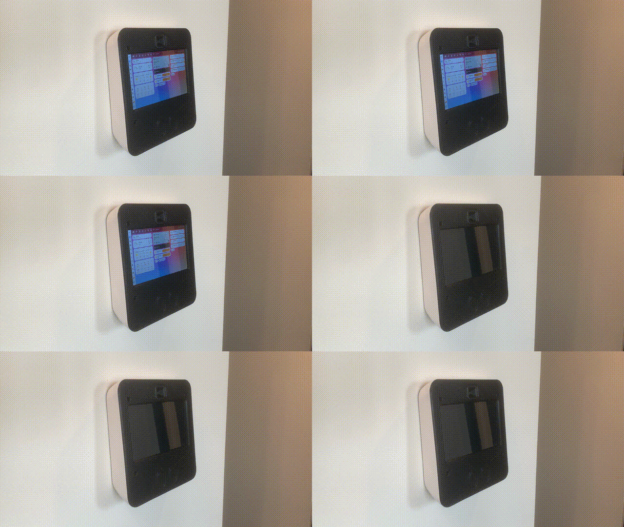
And while we're looking at animations, here's what it looks like when the presence sensor detects that I've walked away, and slowly turns of the screen backlight:

Instead of reading the touch sensor buttons in a Python script, it was easier to use a dti_overlay to tell the RPi to treat the GPIO input like a keyboard press - so that when the sensor is pressed, it is just like pressing the KEY_NEXTSONG key on a keyboard. The next step was configuring Wayfire to know that it should switch workspaces when this key is pressed.
Another really important feature I wanted is for all of my desired apps/browsers/windows to open automatically when the RPi boots up. Ideally this would also include the apps being set up in the right workspace, but so far that has proved challenging, and something I'm still working on.
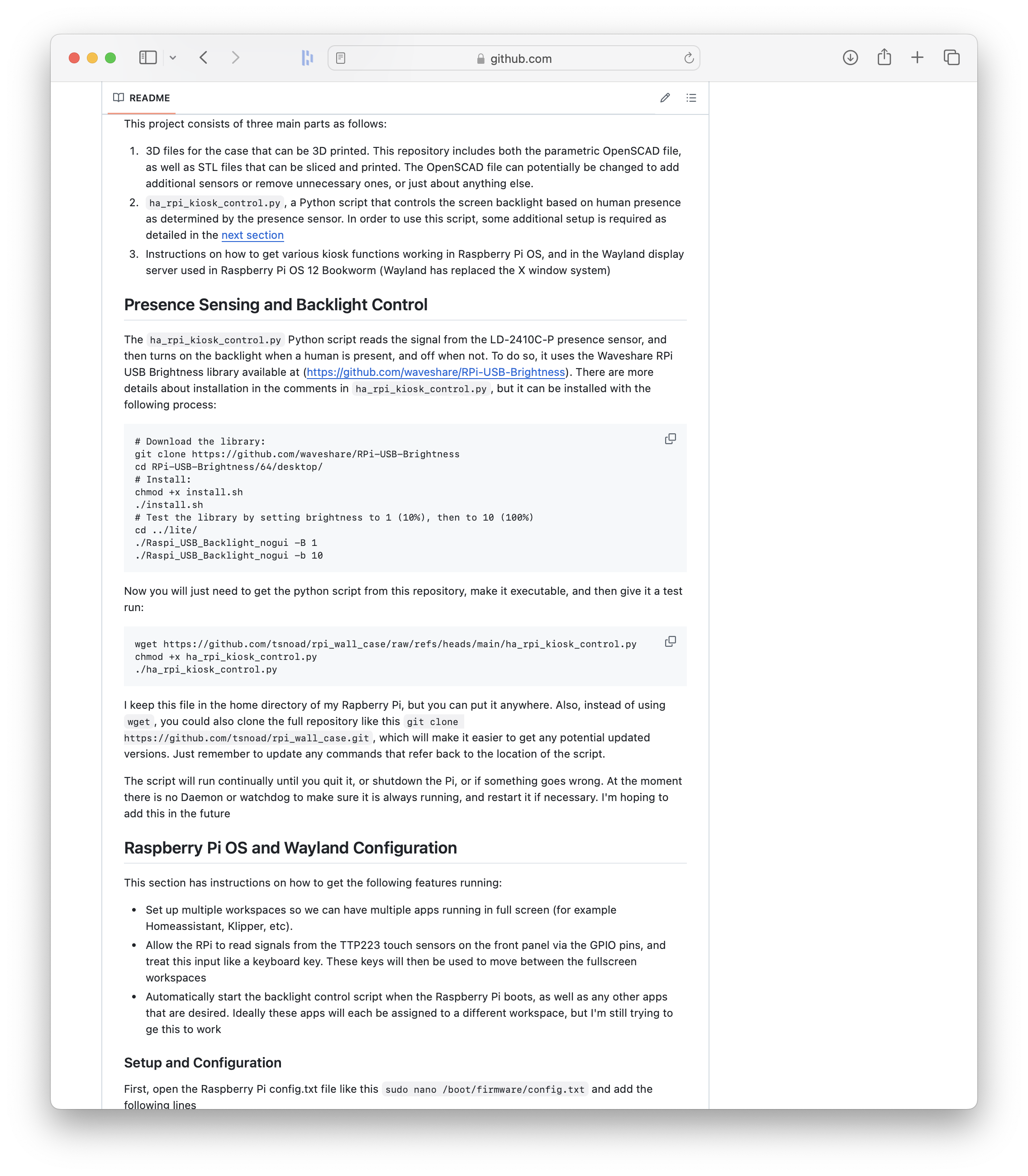
So, how is all of this set up? I've added all of the steps to the README on the GitHub page, which you can find here: https://github.com/tsnoad/rpi_wall_case


So, what's next? To be honest, I'm really not happy with how the front panel looks when it's 3D printed, mainly because of the printer bed texture. At some point I want to redesign the 3D files, which could also include adding a ambient light sensor, but don't expect this soon. With the exception of getting the autostart script to put the windows where I want them, this project is pretty much complete.
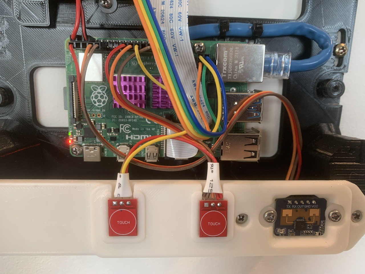
Finally, @ryan-worrell asked how the presence and touch sensors are wired to the GPIO pins, and unfortunately this isn't really something I've documented yet. Here's a (not very useful) picture of the wiring, as well as a (hopefully more useful) table of the pin connections:

| RPi 4 GPIO Pin # | Pin Desc | Connected to |
|---|---|---|
| 1 | 3.3V | VCC pin of LD2410C-P presence sensor |
| 3 | GPIO 2 | Not used |
| 5 | GPIO 3 | Not used |
| 7 | GPIO 4 | OUT pin of LD2410C-P presence sensor |
| 9 | GND | GND pin of LD2410C-P presence sensor |
| 11 | GPIO 17 | Not used |
| 13 | GPIO 27 | Not used |
| 15 | GPIO 22 | Not used |
| 17 | 3.3V | VCC pin of both TP223 touch sensors |
| 19 | GPIO 10 | I/O pin of right TP223 touch sensor |
| 21 | GPIO 9 | I/O pin of left TP223 touch sensor |
| 23 | GPIO 11 | Not used |
| 25 | GND | GND pin of both TP223 touch sensors |
 Tobias
Discussions
Become a Hackaday.io Member
Create an account to leave a comment. Already have an account? Log In.