Close
0%
0%

Raspberry Pi 1000

Raspberry Pi 5-based all-in-one PC inside a keyboard!

Public Chat
Similar projects worth following
Greetings to everyone, and welcome back.

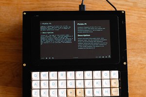
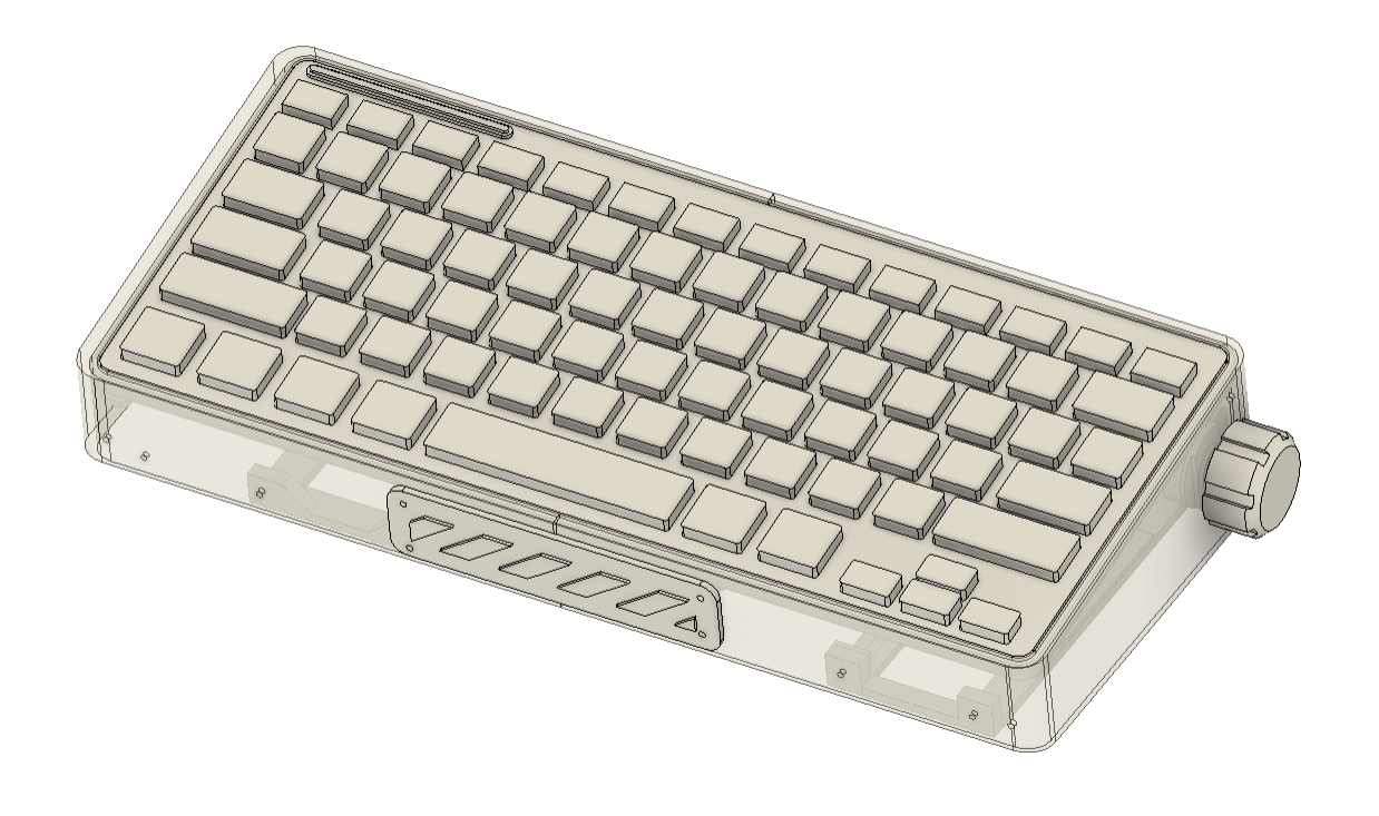
Here's something fun: the Pi1000, the newly created Raspberry Pi 400 DIY Alterative, a portable keyboard-computer that combines a Raspberry Pi setup with a keyboard.
Here, we are utilizing the new PCIE M.2 Shield coupled with the NVME SSD and Raspberry Pi 5 4Gb Version.

Our version, like the Raspberry Pi 400, has a whole Raspberry Pi setup packed inside a keyboard.

It takes about 5–6 seconds for this setup to boot to the desktop, which is incredibly quick thanks to the new Raspberry Pi 5 paired with the NVME SSD.

Here, we are using a Gen 3x4 SSD that supports PCIE Express 3.1 and can provide read/write speeds up to 1600 to 1100 MB/s.

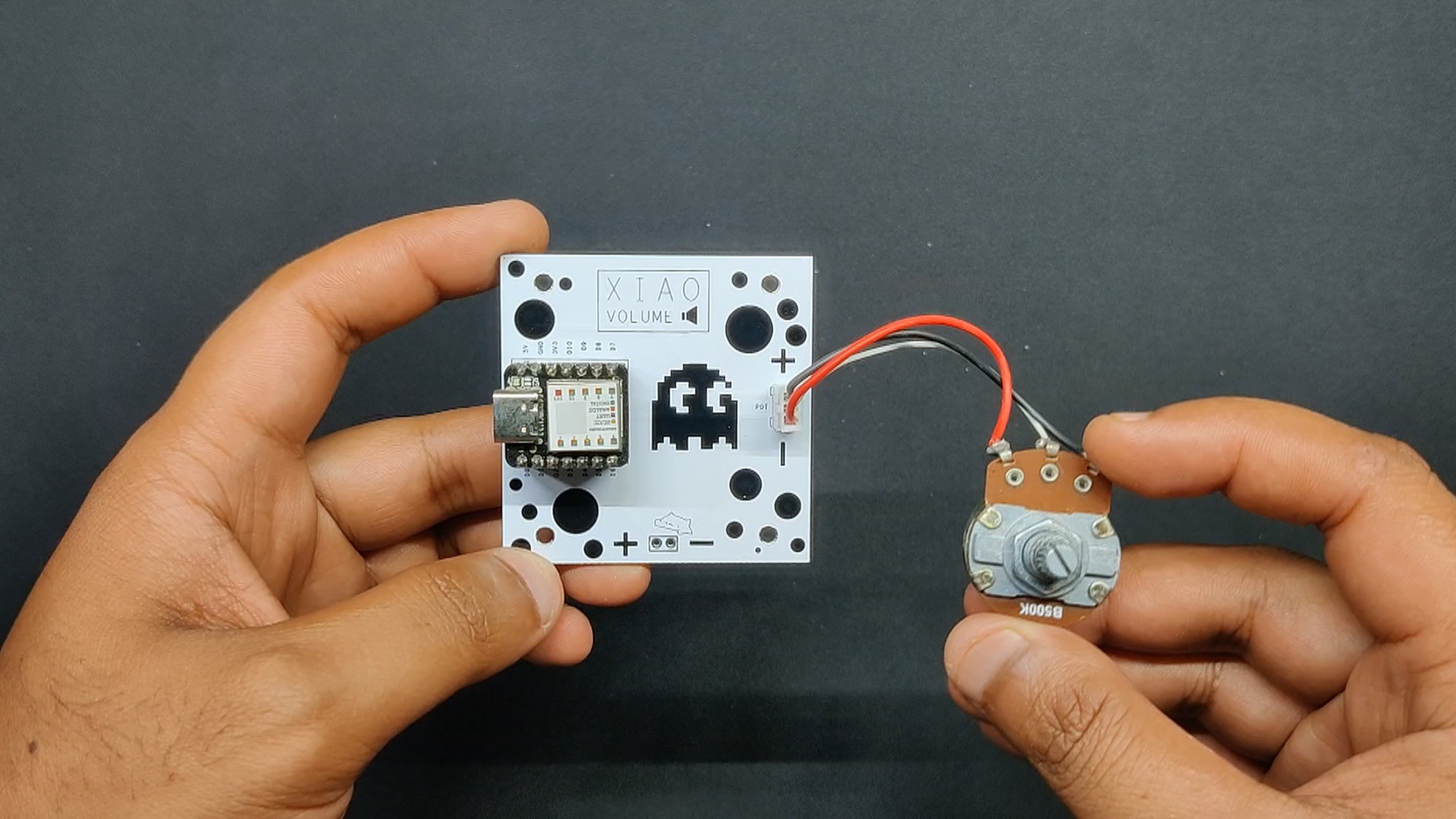
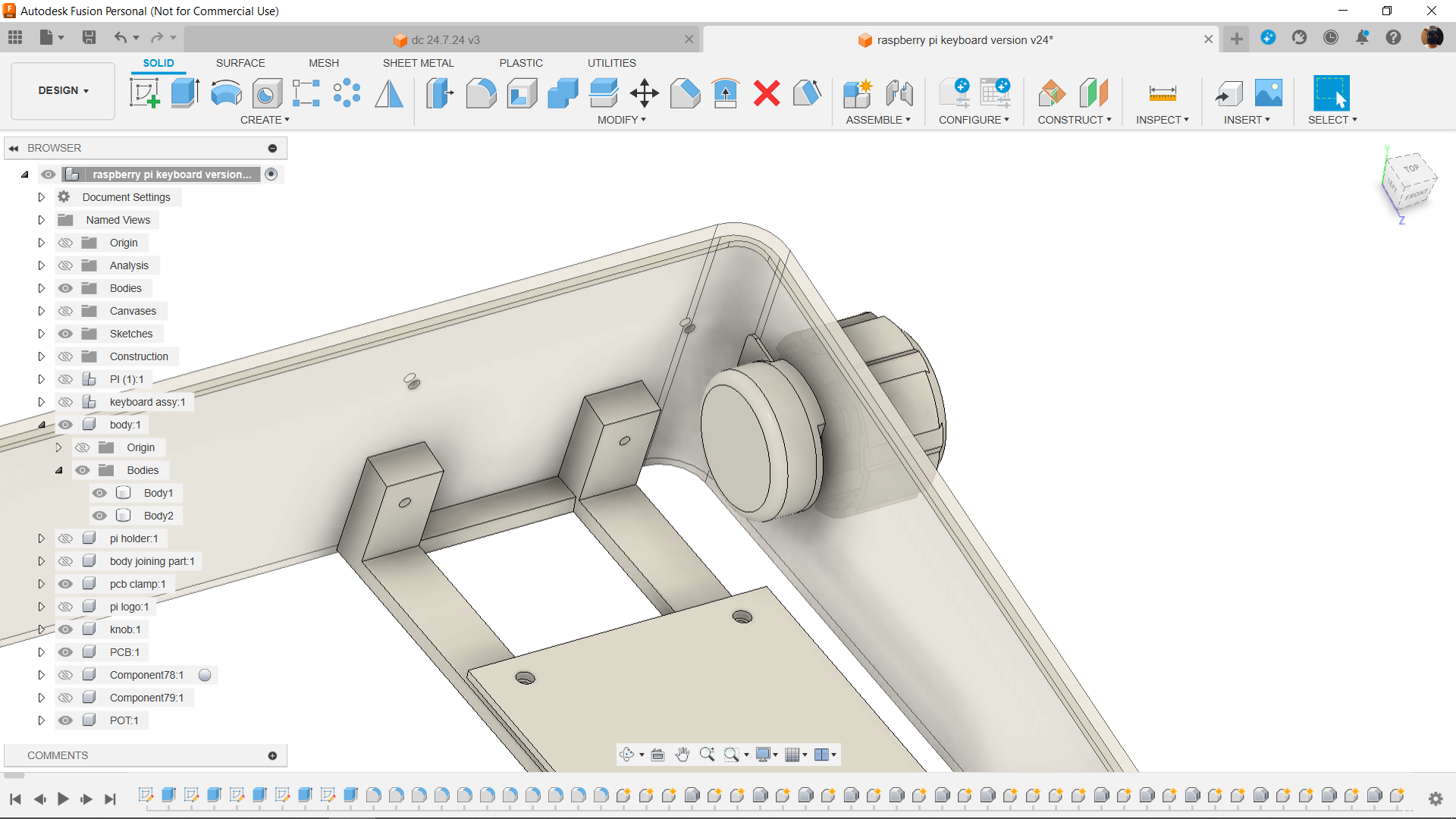
We have added a custom Volume Knob controller, which was also created from scratch using a Seeed's XIAO SAMD21 Microcontroller and uses the HID protocol to control the system volume, in addition to the new Raspberry Pi 5 setup.

Design-Concept

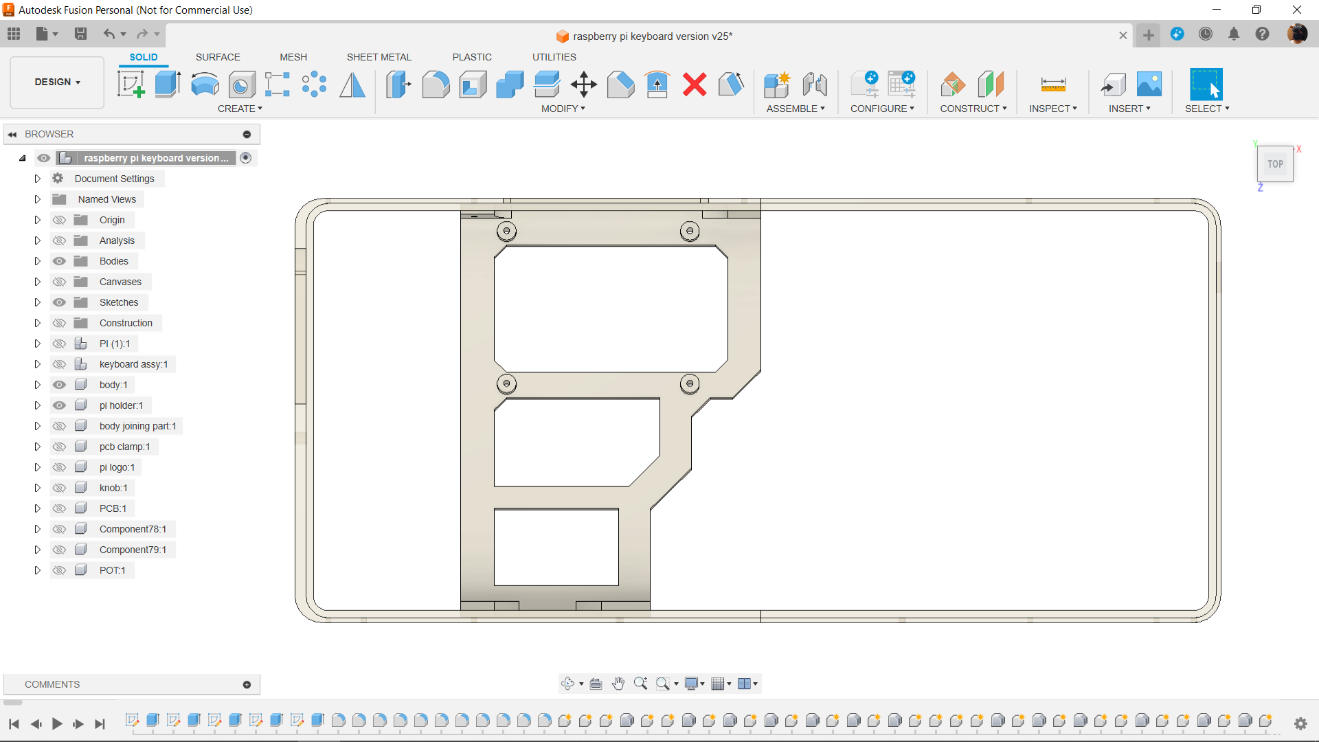
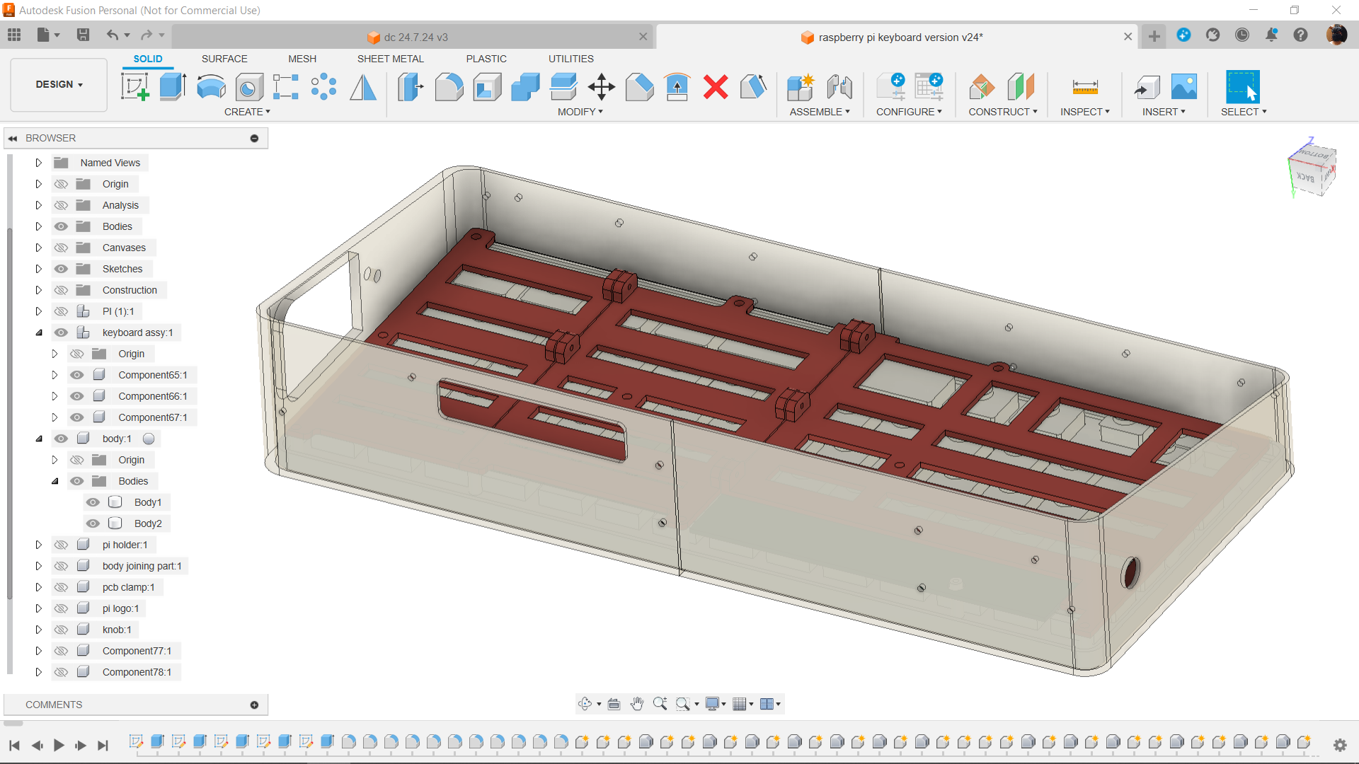
First, we use our Fusion360 engineering software to create a model of our keyboard. We do this by meticulously measuring the keyboard's size, placement of the keys, and other details.

Keyboard modeling was essential since it helped us create the frame that surrounds the keyboard.

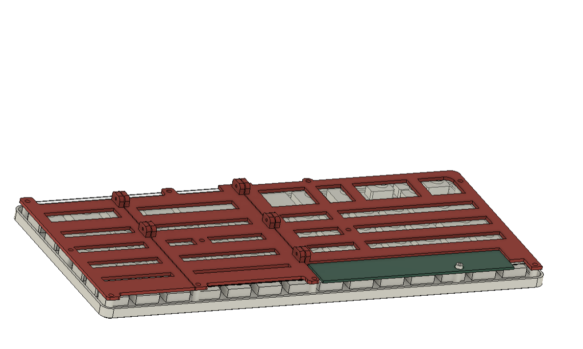
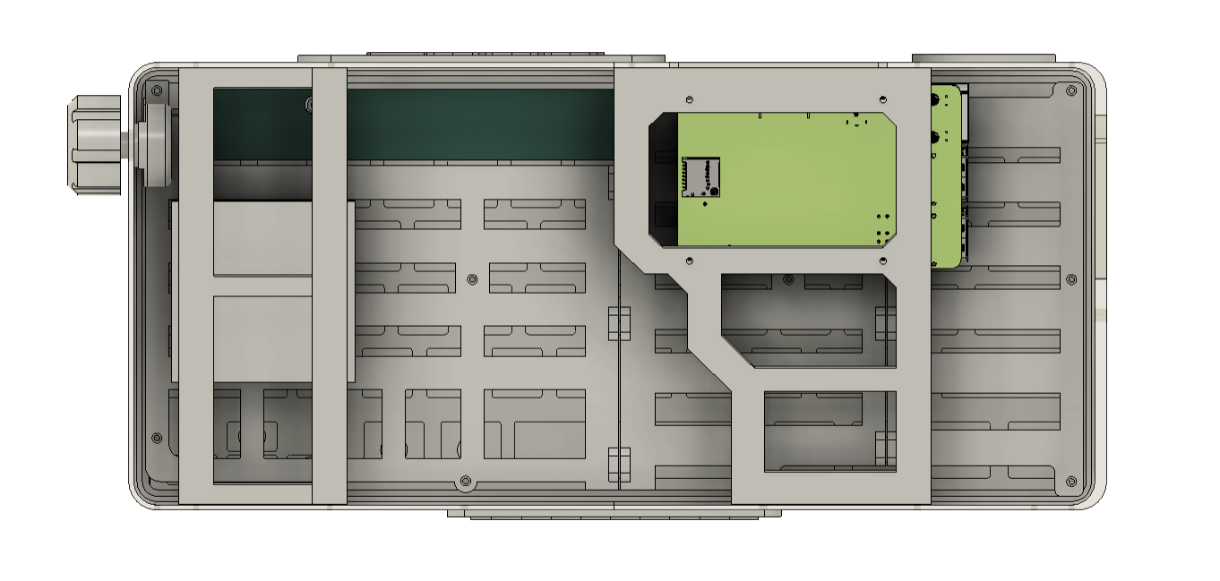
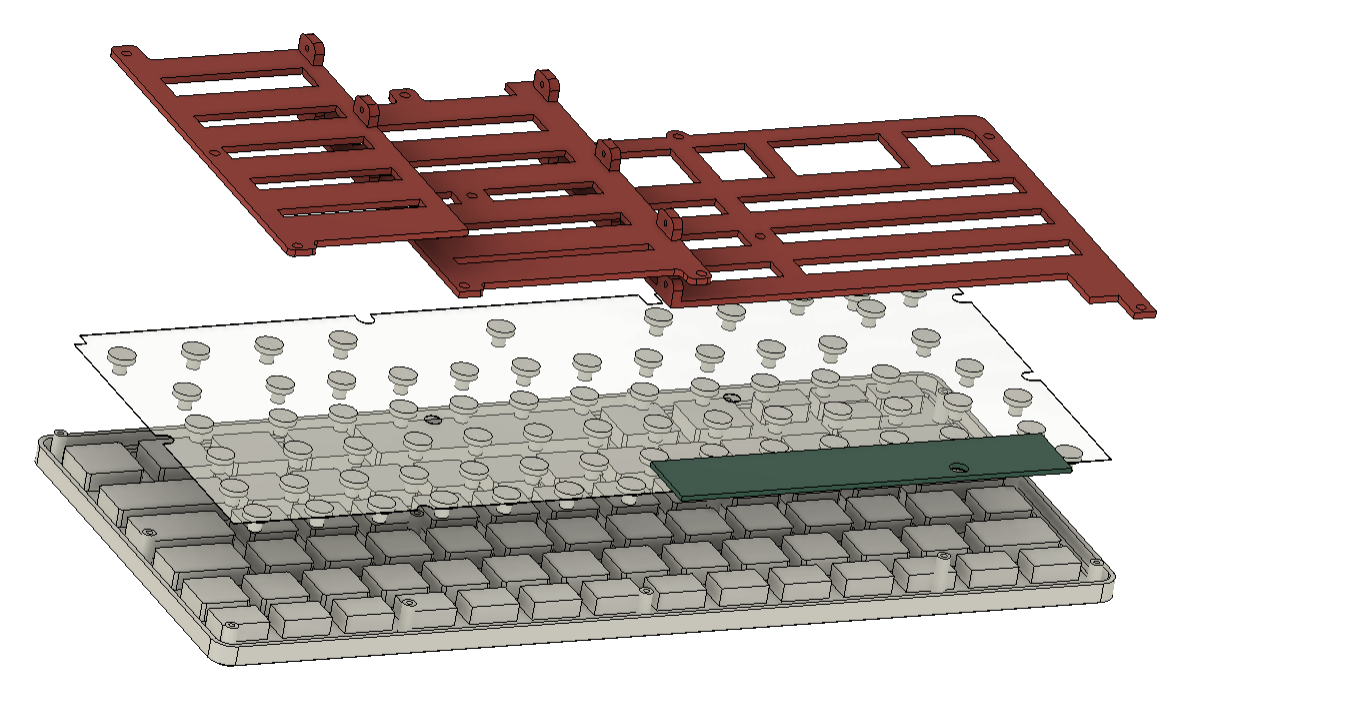
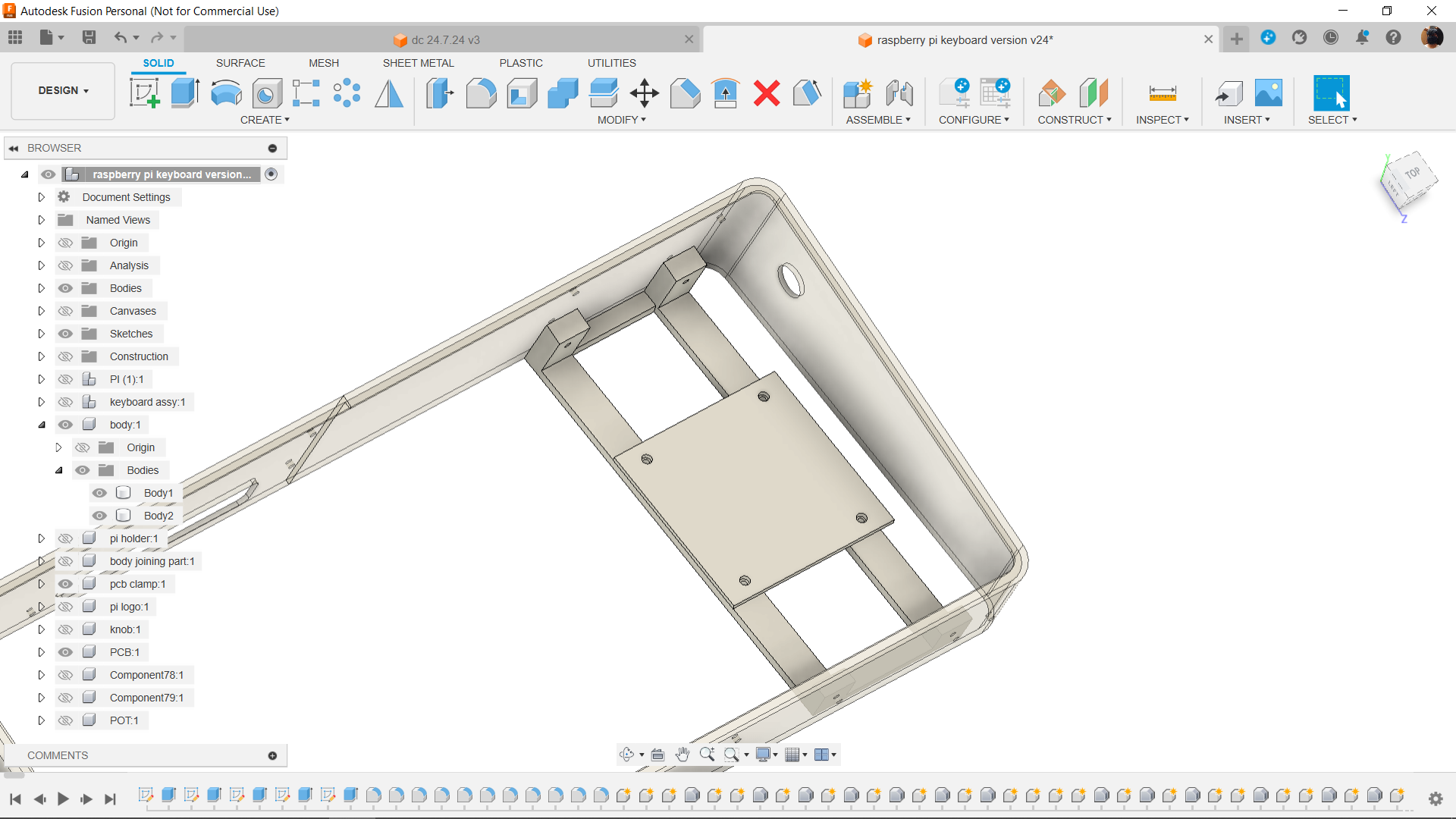
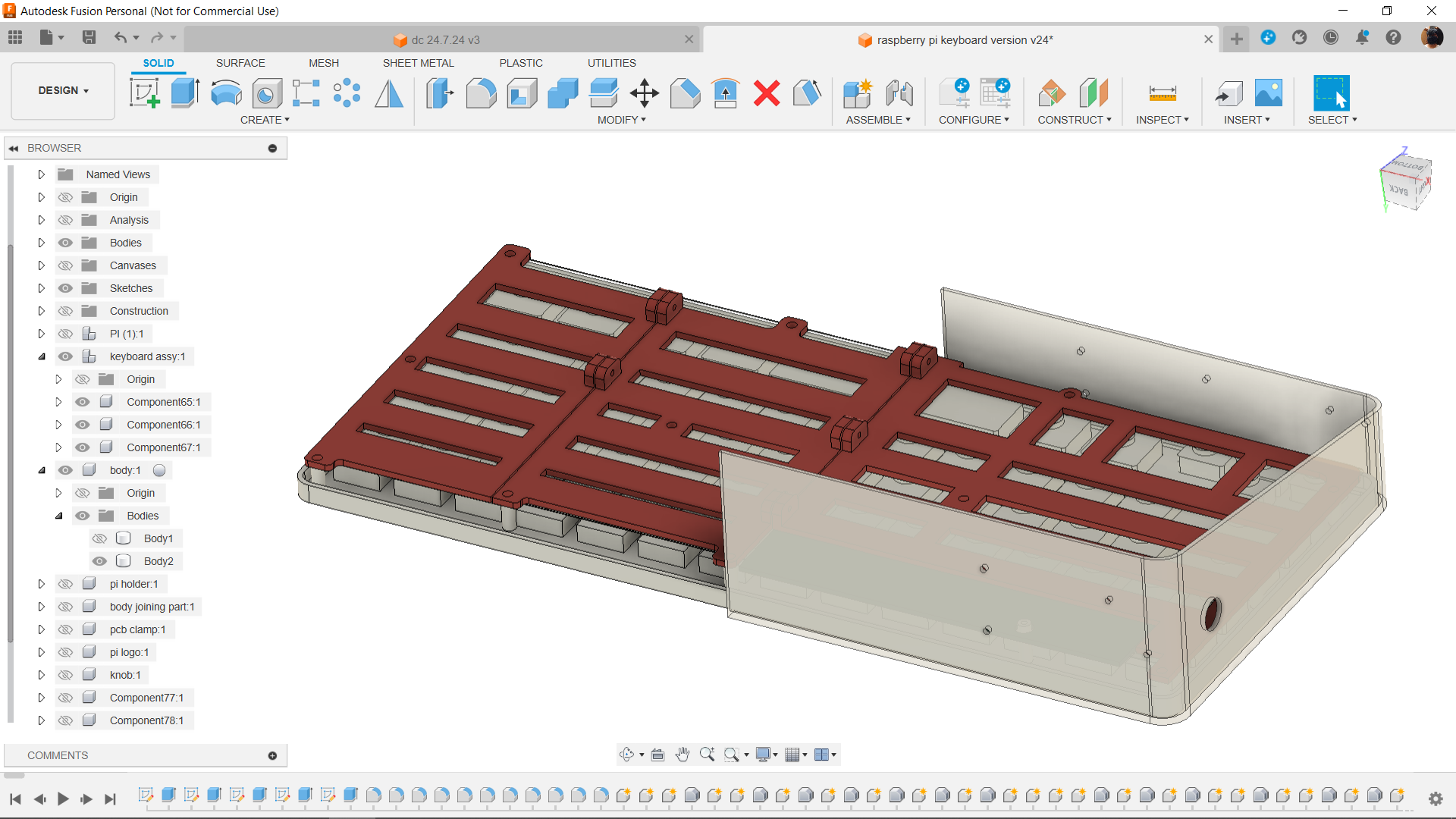
Three keyboard holder components have been added to the rear of the keyboard; they are used to secure the keyboard membrane in place. The holders are tightened onto the screw bosses that are already present on the keyboard.

The frame section and the holder section made up the majority of the main model.

The frame is further separated into the left and right frame sections.

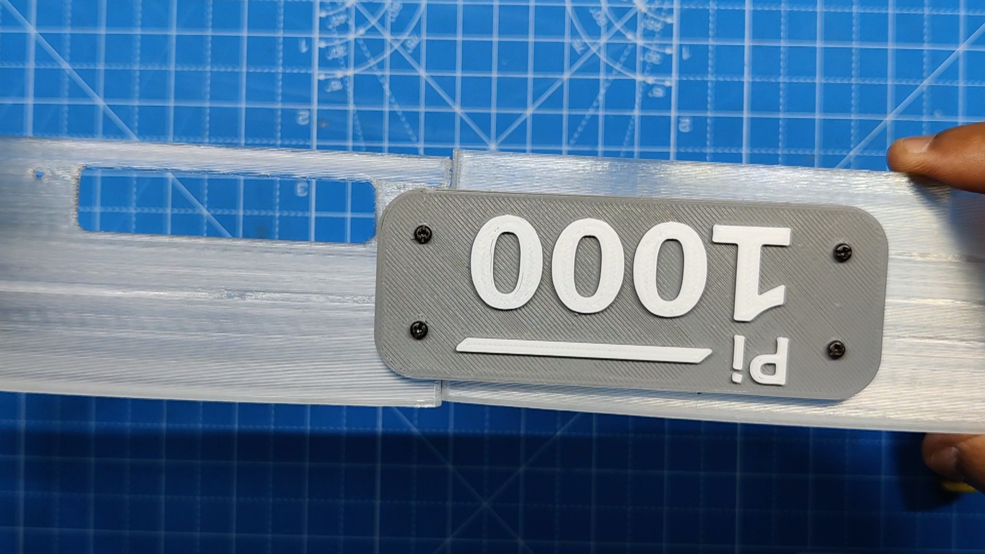
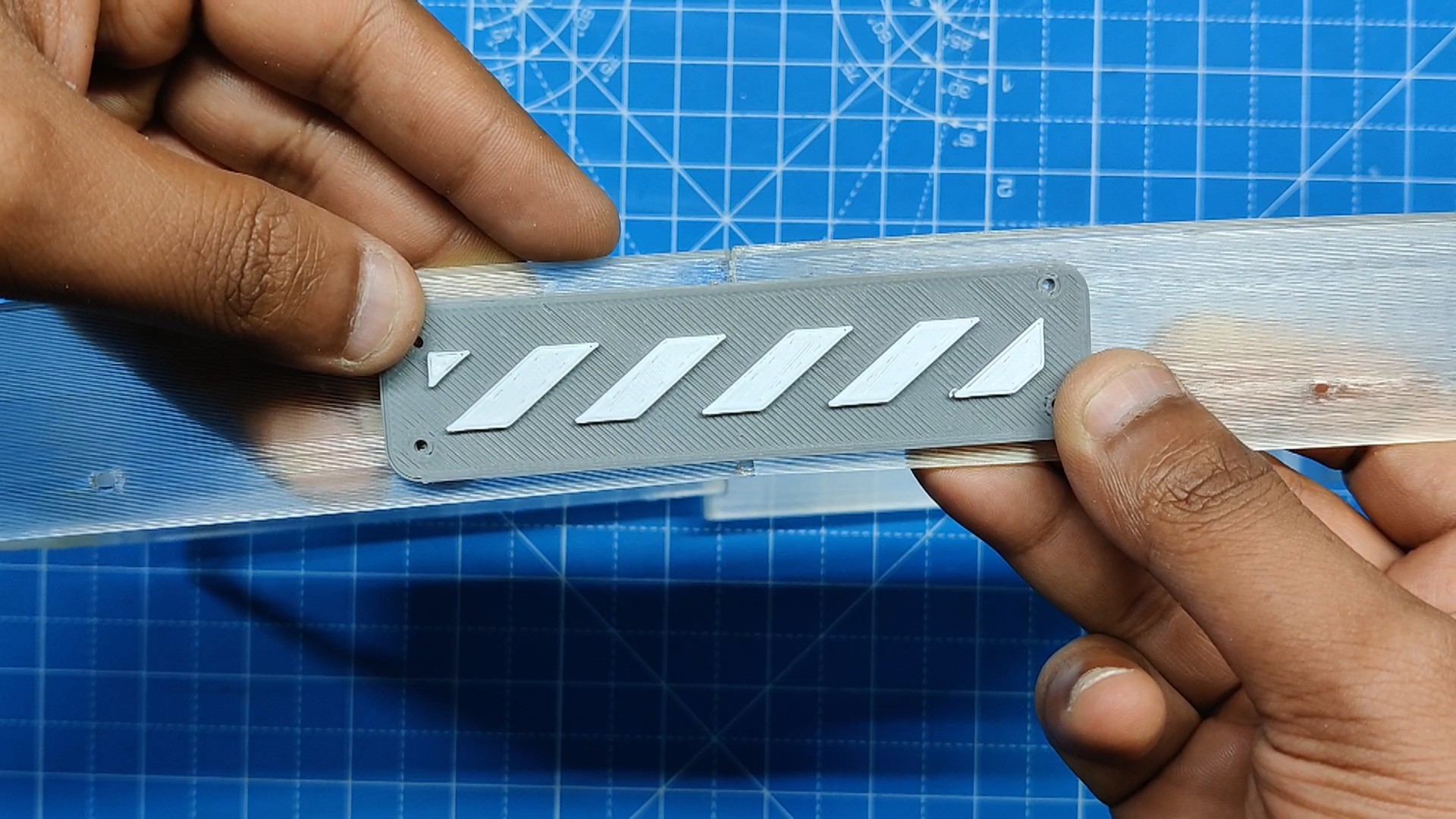
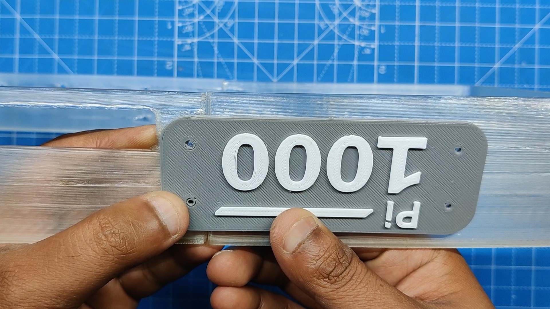
Two logo components and four M2 screws are used to join the frame together.

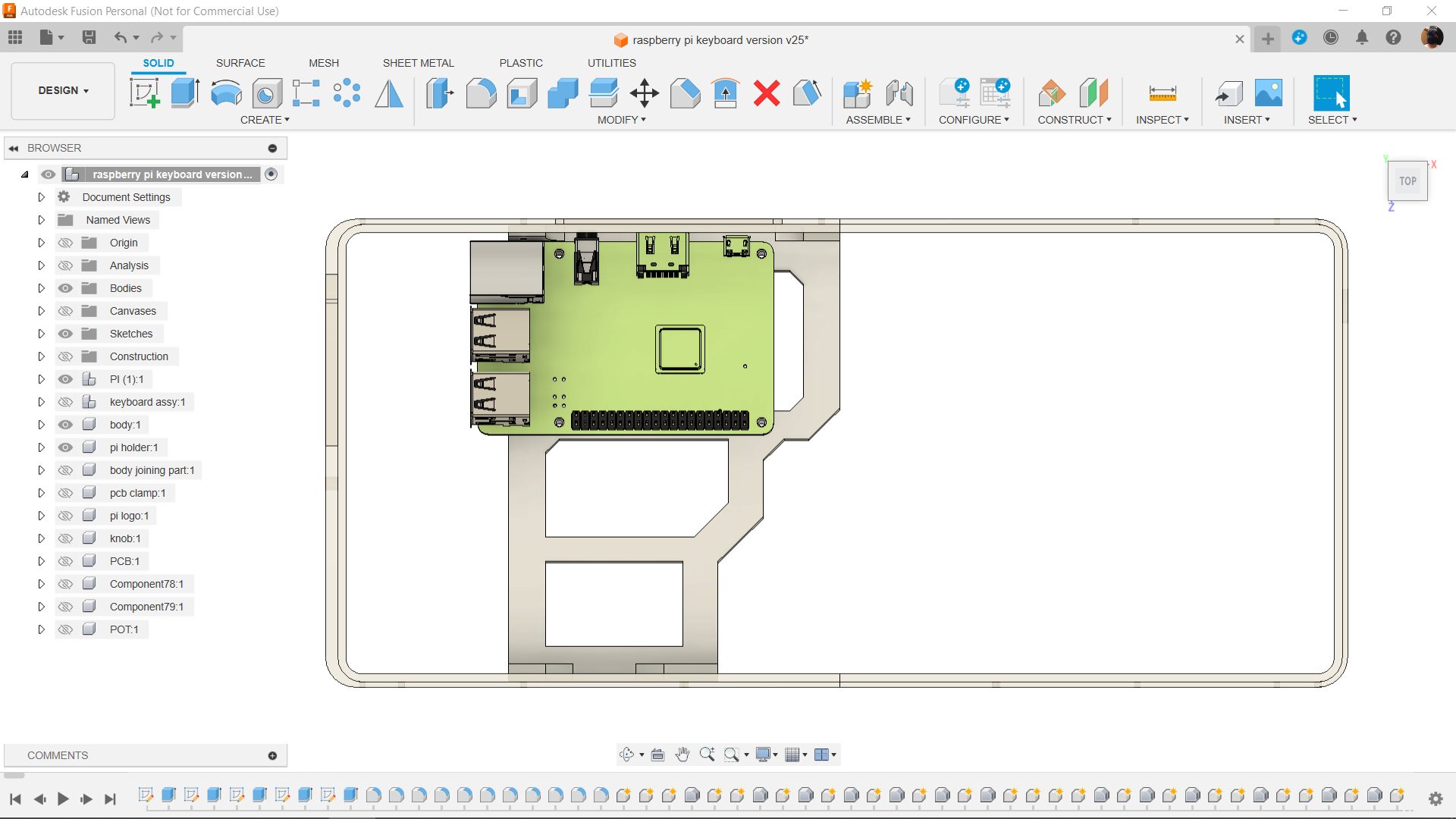
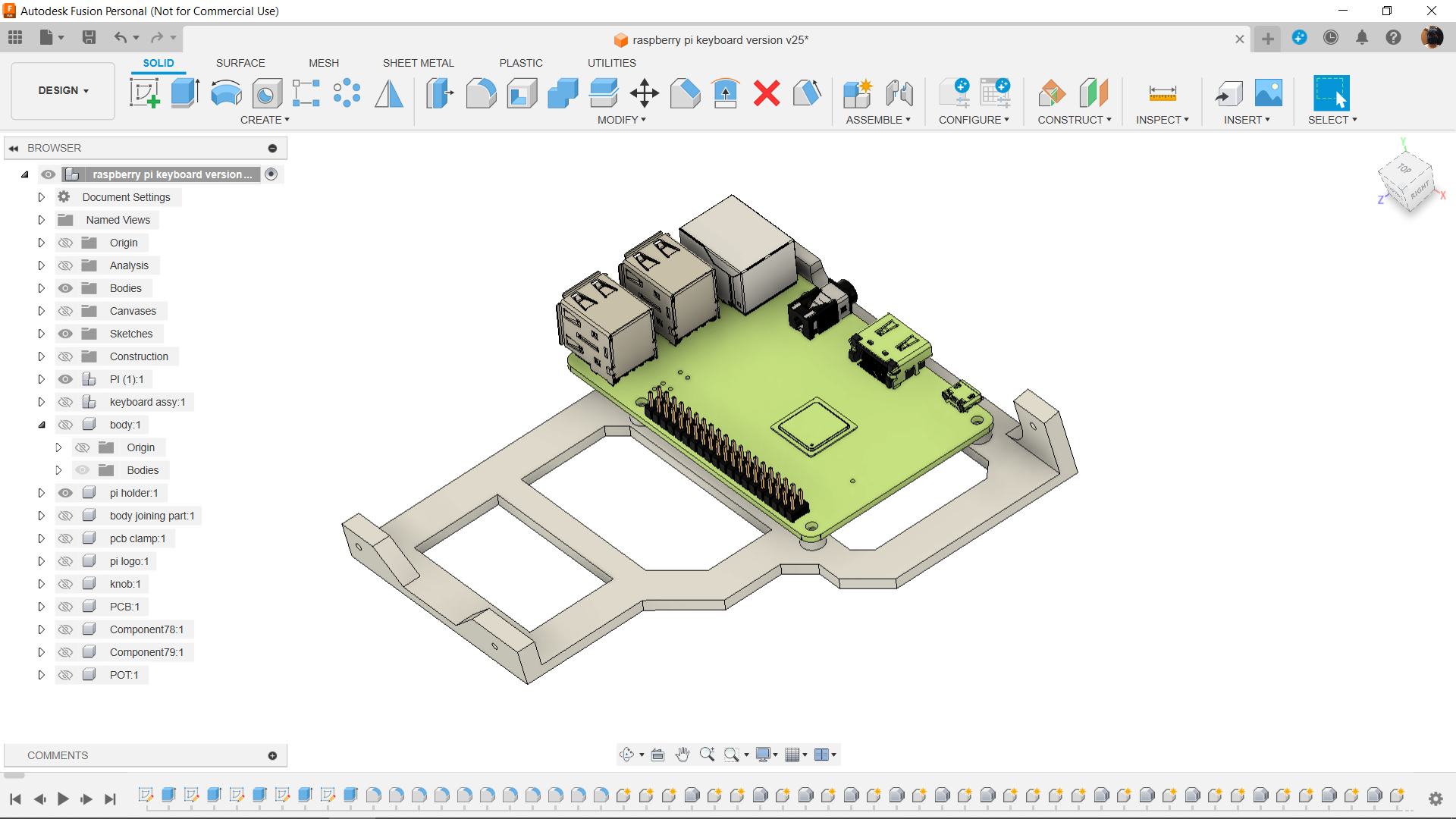
One of the two holders is used to secure the Pi in place, and the other holds the volume control circuit.

In addition, we incorporated a model of an accent section that was borrowed straight from the Dragon Ball series' Capsule Corp logo to give this keyboard model a faintly sci-fi feel. After the model was finished, it was exported into mesh files for 3D printing, using a single 0.6mm nozzle, 20% infill, and 0.2mm layer height.

We utilize clear PLA for the frame, orange PLA for the keyboard holder, and grey PLA for the pi holder.

XIAO HID Volume Knob
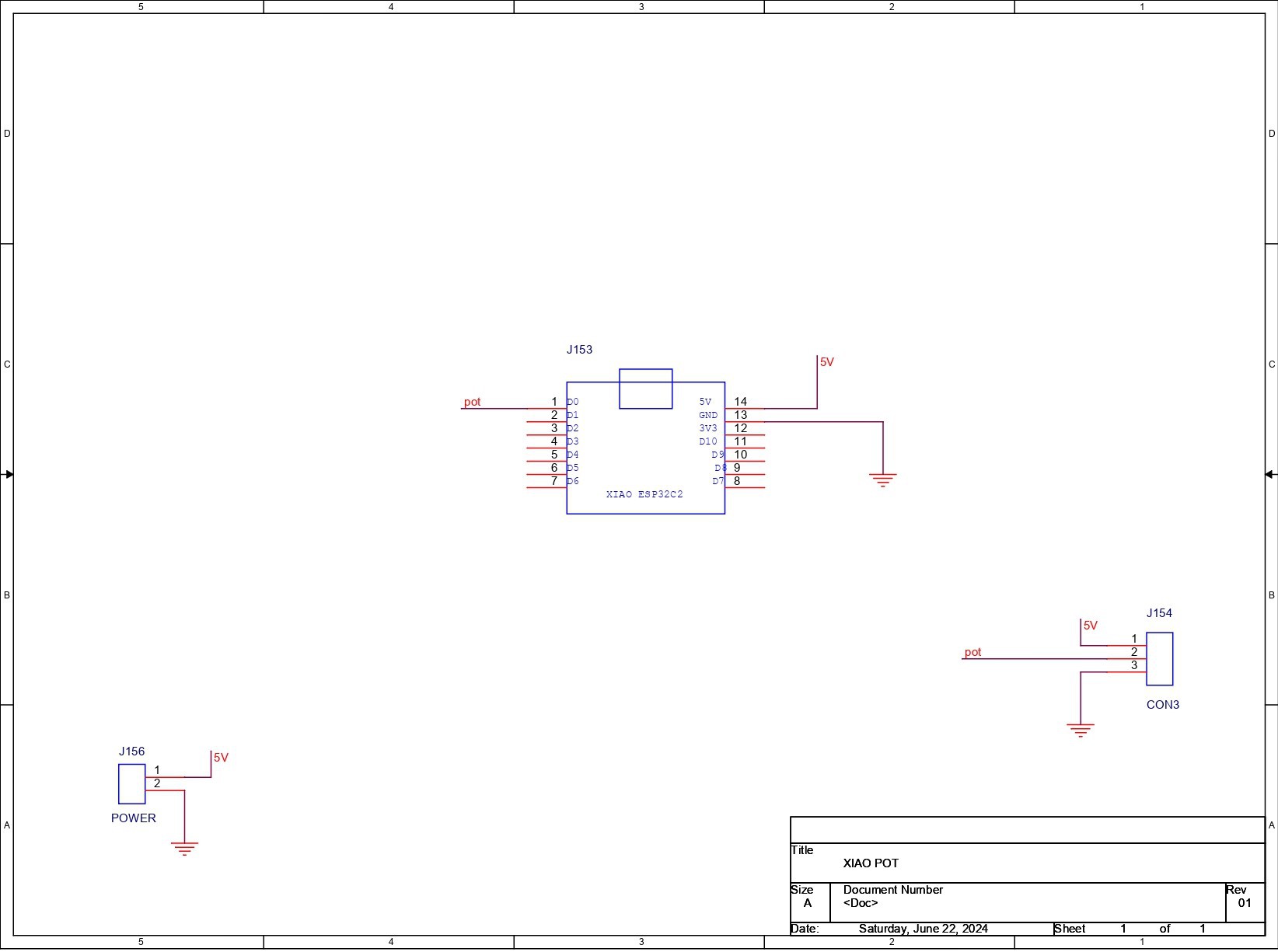
First, we created the schematic, which included a potentiometer and an XIAO SAMD21 microcontroller attached. Here, we are using a CON3 JST connector that is linked to GND, D0, and VCC. We will be using this connector to add a potentiometer to our XIAO.

Additionally, CON2, which is connected to XIAO's VCC and GND, is added.

There is no need for batteries or a power circuit because we will be directly connecting the XIAO and Raspberry Pi through the USB port to provide power.

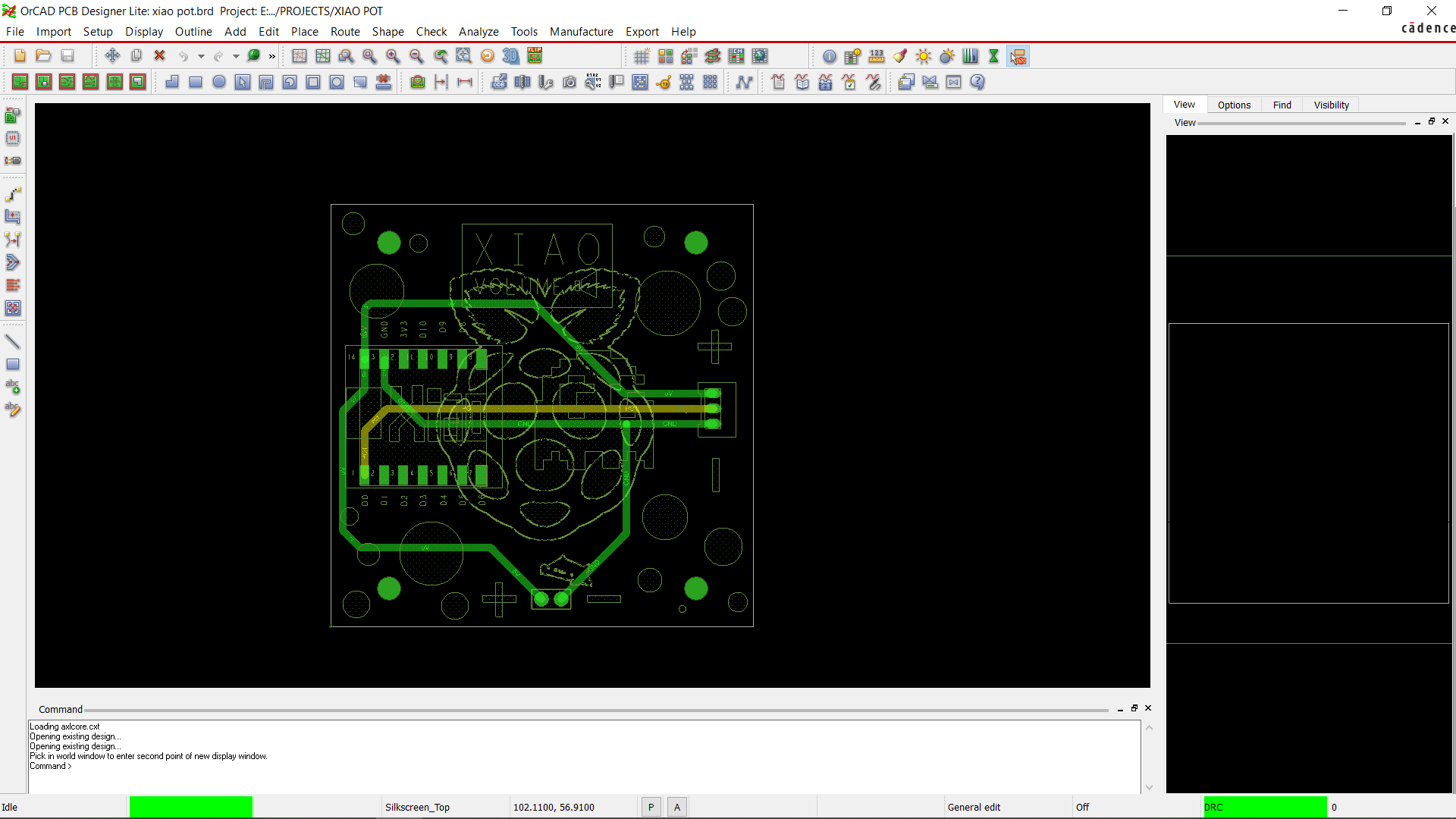
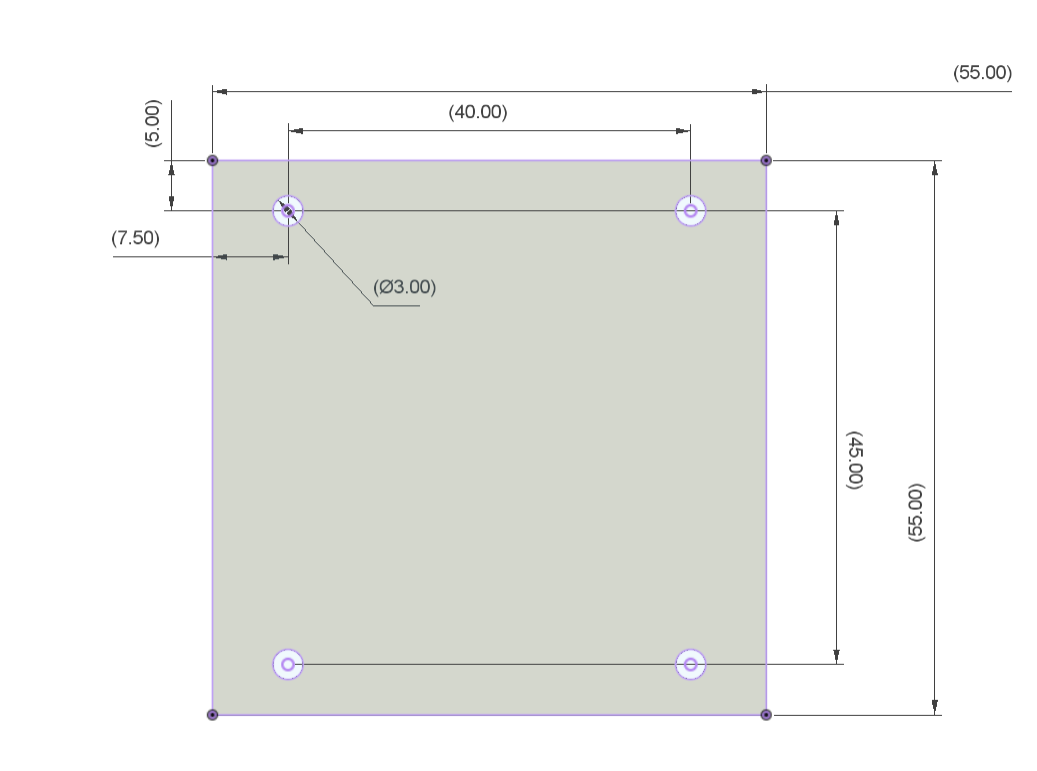
We utilize the CAD file's measurements for the layout, which include the location of the XIAO and the mounting holes.

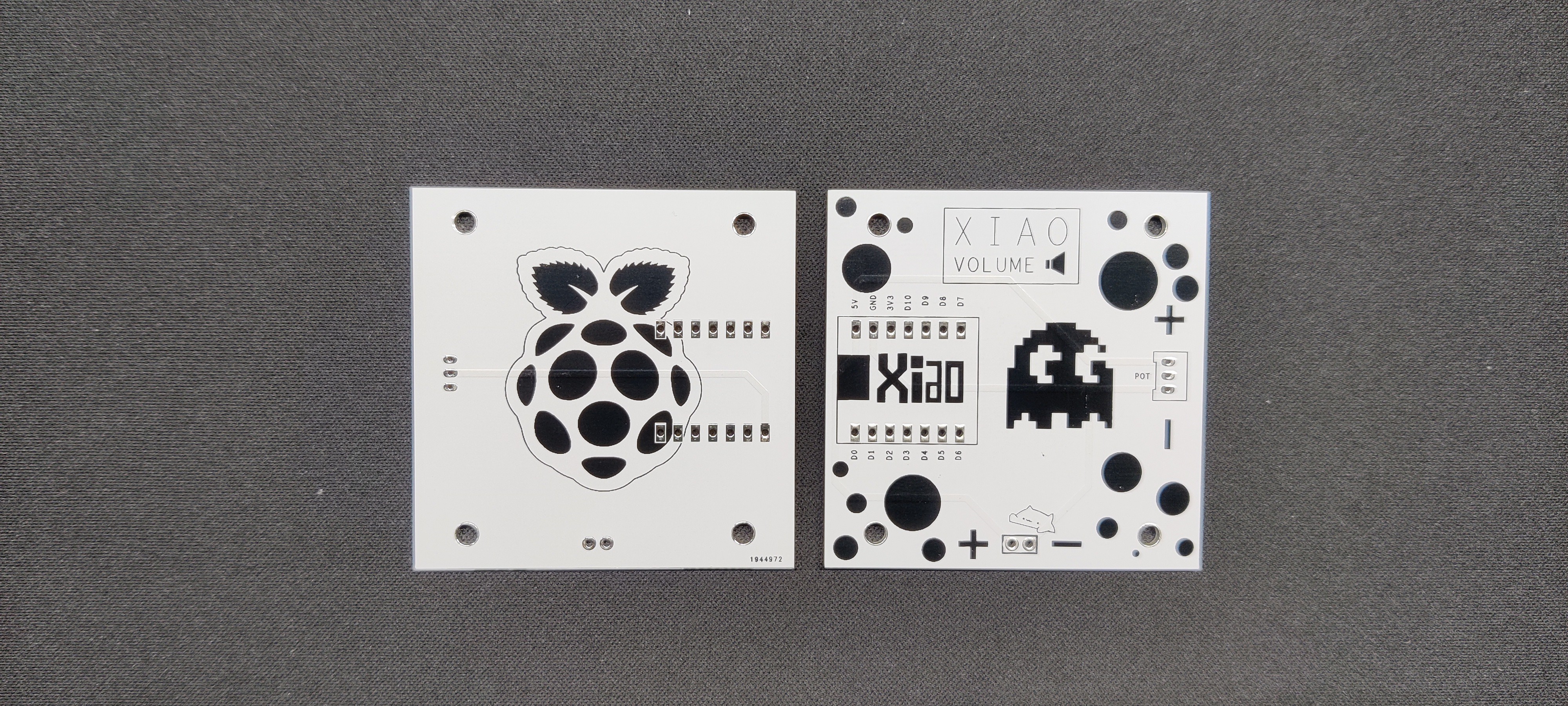
In addition, we added some attractive graphics to the PCB's top and bottom sides.

Seeed Studio Fusion
This project was made possible because of support from Seeed Studio Fusion.

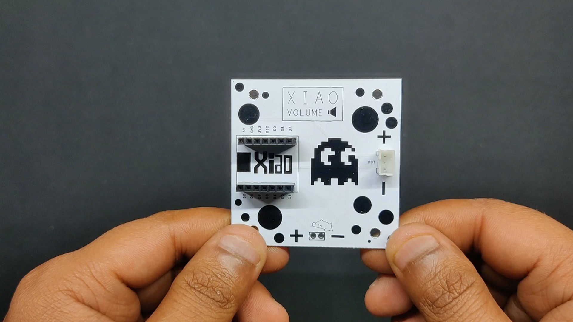
We finished the PCB design, produced the Gerber data, uploaded the file to their quote page, and placed an order for the PCB with black silkscreen and white solder mask.

PCBs were received within a week, and the quality was super good considering the price, which was also pretty low.

Seeed Fusion offers one-stop prototyping for PCB manufacture and PCB assembly, and as a result, they produce superior-quality PCBs and fast-turnkey PCBA within 7 working days.

Seeed Studio Fusion PCB Assembly Service takes care of the entire fabrication process, from PCB manufacturing to parts sourcing, assembly, and testing services, so you can be sure that they are getting a quality product.

After gauging market interest and verifying a working prototype, Seeed Propagate Service can help you bring the product to market with professional guidance and a strong network of connections.

raspberry pi keyboard version v25.f3d

fusion - 20.72 MB - 07/26/2024 at 15:11

Download

raspberry pi keyboard version v25.step

step - 17.92 MB - 07/26/2024 at 15:11

Download

POT.pdf

Adobe Portable Document Format - 149.83 kB - 07/26/2024 at 15:11

Preview

pi holder.stl

Standard Tesselated Geometry - 162.19 kB - 07/26/2024 at 15:11

Download

BOADY PART1.stl

Standard Tesselated Geometry - 120.39 kB - 07/26/2024 at 15:11

Download

View all 13 files

  • 1
    PCB Assembly

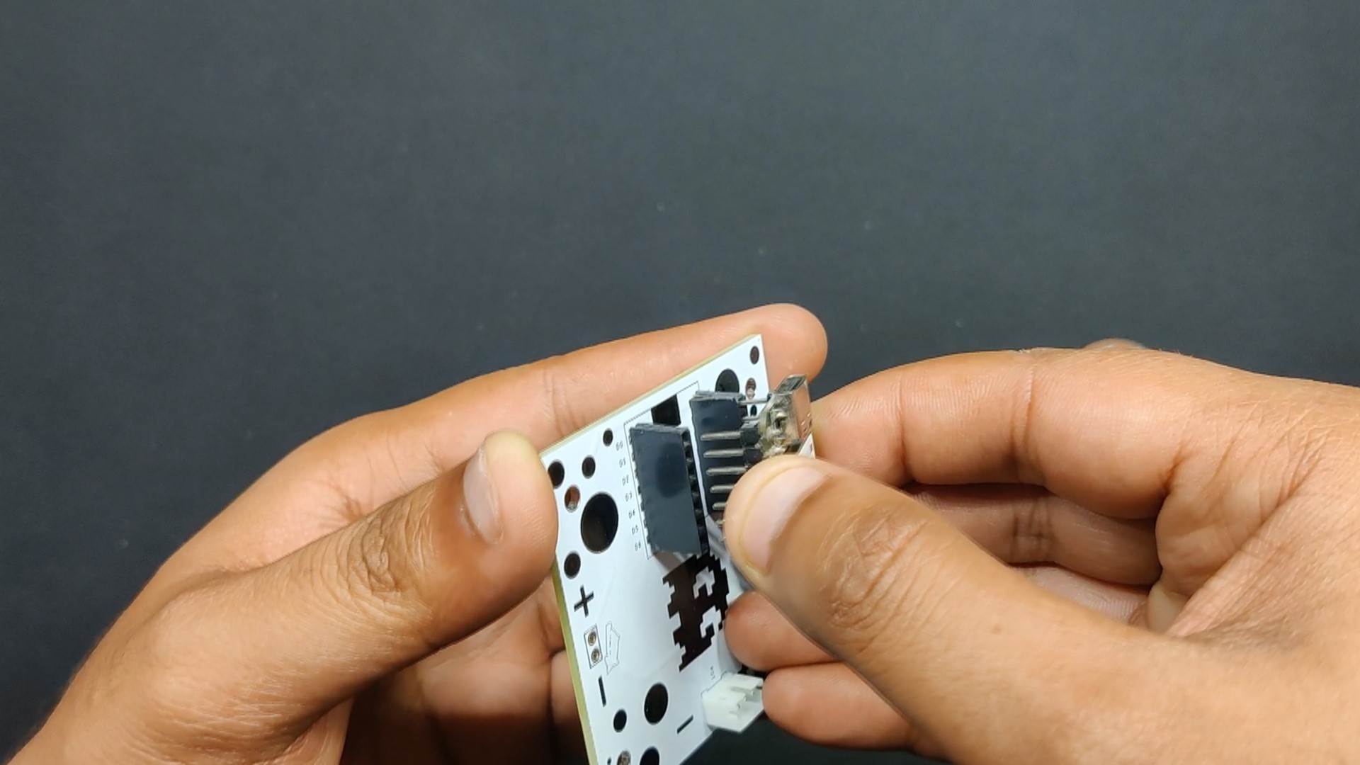
    The assembling process was not too difficult because this PCB is a through-hole board without any SMD components.

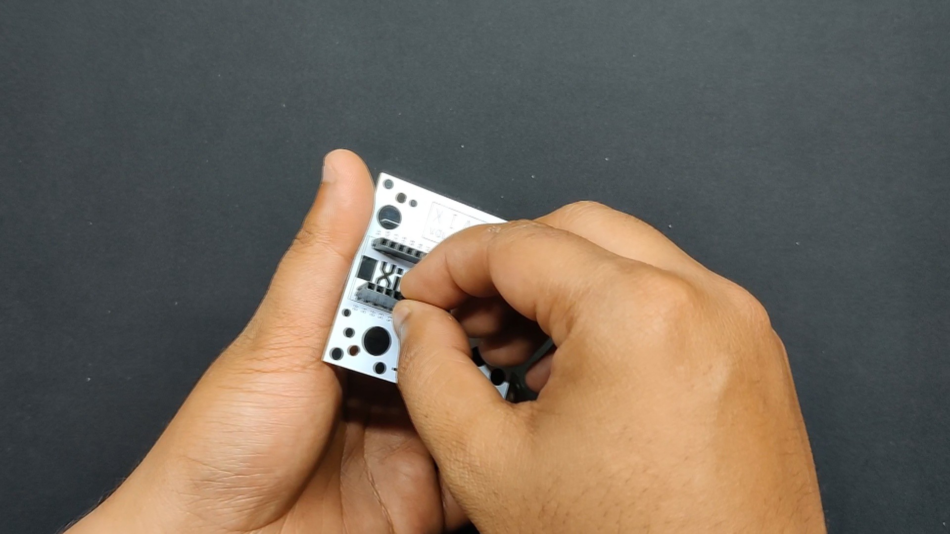
    First, we installed two CON7 header pin sockets in their place, and after that, we added the CON3 UC203 connector to the PCB.
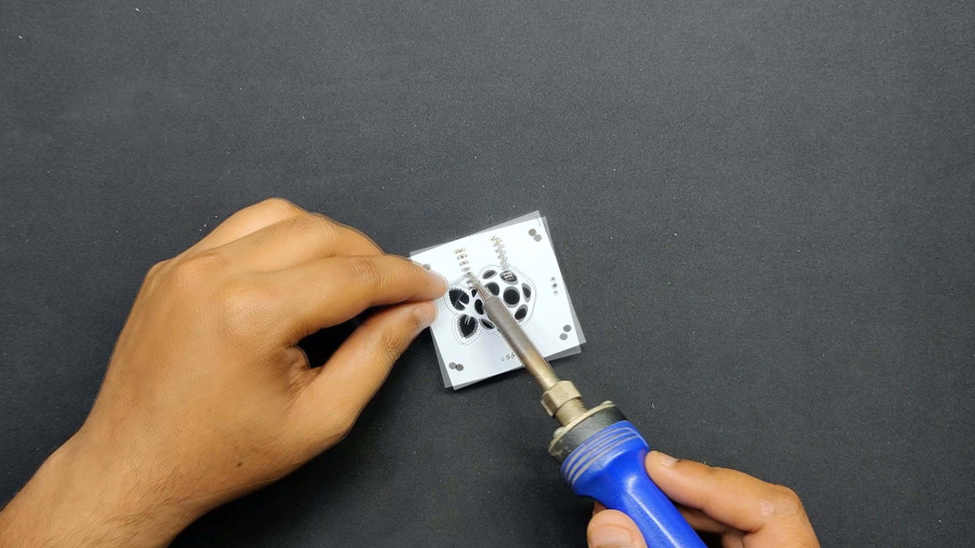
    Next, we use a soldering iron to solder the CON7 and CON3 pads.
    Next, we align the XIAO with the two CON7 header pins and connect the potentiometer's wire harness to the CON3.

  • 2
    CODE

    Here's the sketch that we used in this project to control the PC's volume, and it utilizes the HID protocol using an XIAO microcontroller. This was because of the microchip's SAMD21G18 inside the XIAO SAMD21.

    #include <HID-Project.h> //include HID_Project library
    #include <HID-Settings.h>
    #define REVERSED false           
    
    int val = 0;
    int previousval = 0;
    int val2 = 0;
    void setup() {
    Consumer.begin();                         //initialize computer connection
    delay(1000);                              //wait for computer to connect
    for(int a = 0; a < 52; a++) {
    Consumer.write(MEDIA_VOLUME_DOWN);      //set the volume to 0
    delay(2);
    }
    }
    void loop() {
    val = analogRead(D0);                      //read potentiometer value
    val = map(val, 0, 1023, 0, 101);          //map it to 102 steps
    if(REVERSED) {
    val = 101 - val;
    }
    if(abs(val - previousval) > 1) {          //check if potentiometer value has changed
    previousval = val;
    val /= 2;                               //divide it by 2 to get 51 steps
    while(val2 < val) {
    Consumer.write(MEDIA_VOLUME_UP);      //turn volume up to appropiate level
    val2++;
    delay(2);
    }
    while(val2 > val) {
    Consumer.write(MEDIA_VOLUME_DOWN);    //turn volume down to appropiate level
    val2--;
    delay(2);
    }
    }
    delay(301);                        
    }
  • 3
    Frame Assembly

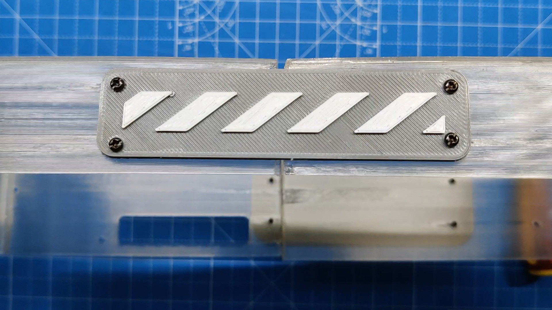
    Prior to beginning the assembly process, we connected the two frames together and joined them from the input side using the Pi1000 logo.

    Four M2 screws are used to fasten the Pi1000 logo to the frame.

    We added an additional logo piece from the other side and used M2 screws to fasten the frame together.

    Here, the Two Logo has two purposes: one, it joins the two frame sections to form a single, large frame; second, it just looks good.

View all 17 instructions

Enjoy this project?

Share

Discussions

Similar Projects

Does this project spark your interest?

Become a member to follow this project and never miss any updates