 Michael Mayer
Summary
This is my Portable Raspberry PI 4 computer. design. Important for me was that the product has a mechanical keyboard. The rest of the design is worked around this keyboard.
Included is the Freecad Project and Step files.
You can find them on Printables.
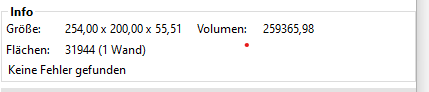
Print Size:
Keyboard considerations
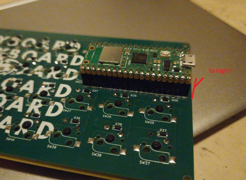
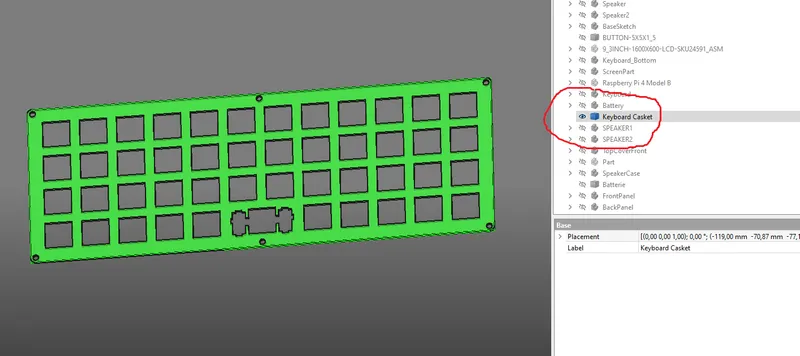
The Keyboard is based on the 40 % Happy key, but the PBC with the 2040 Raspberry will not fit in the case (Height and port position). You may relocate the 2040 Pi and wire it with the PBC. I have printed the included Keyboard Casket and handwired the Keyboard. Is easier than you think. (Little Video). For the keyboard software I use Circuit Python with KMK.
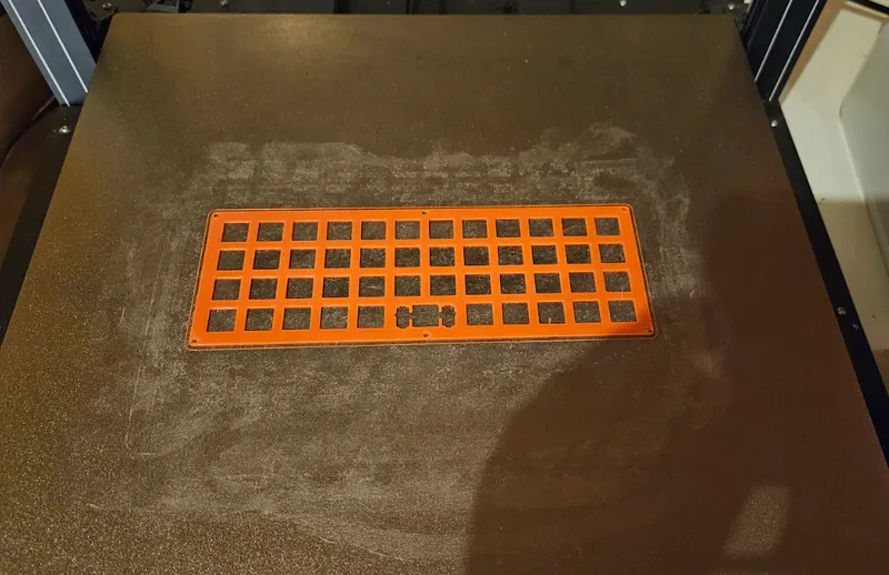
Build:
Print the Casket:
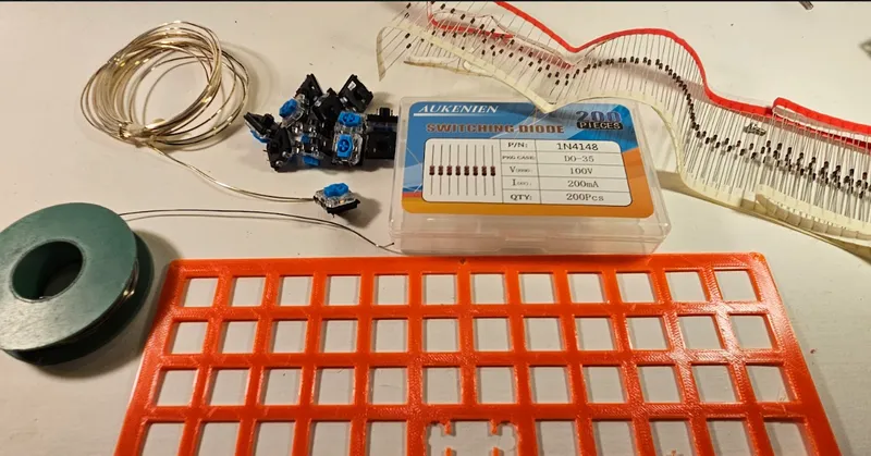
Parts:
Silverwire, Solder&Soldering Iron, Diodes, Keyswitches and patience. And Some wires and the Pico2040 board.
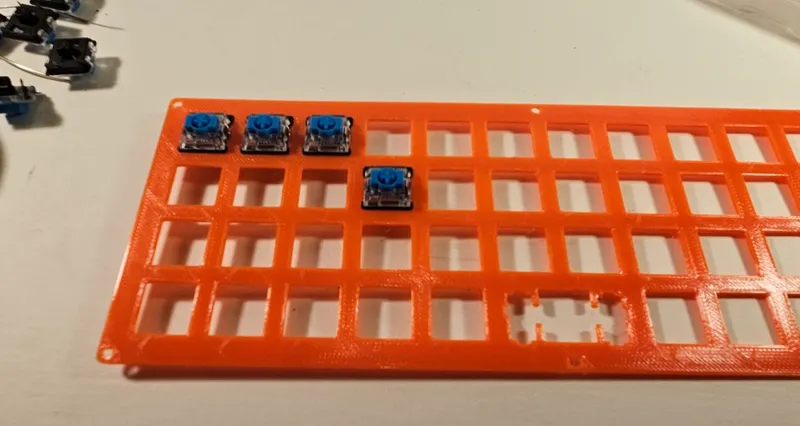
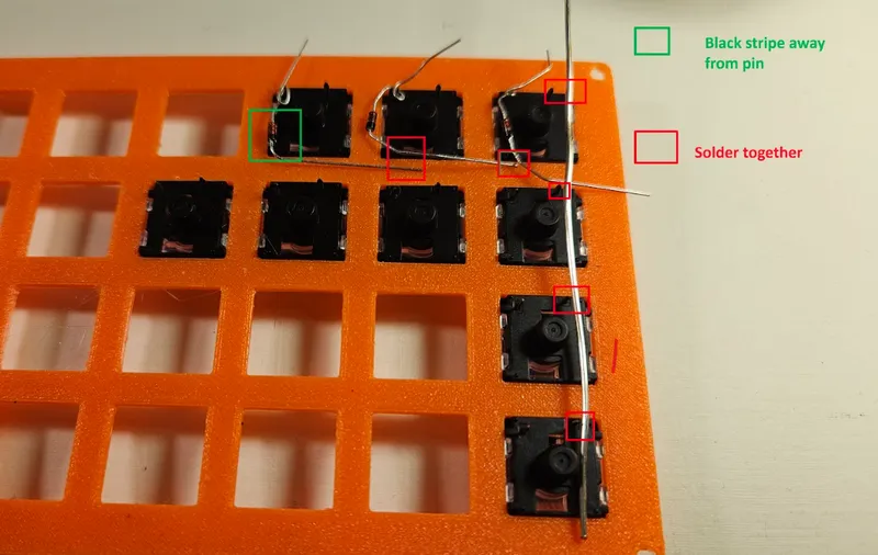
Snap the key switches in.
Solder
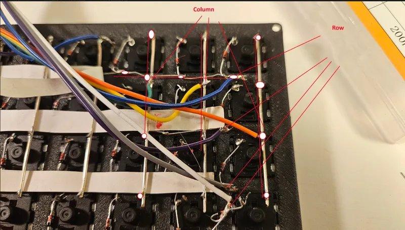
Solder wires to columns and rows and connect them to the Pico 2040
Final:
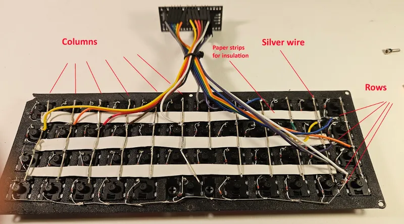
Dont use the presoldered 2040 Board with the PCB. It will not fit. But you may solder wires to the PCB and relocate the 2040 Board.
The code.py configuration is included. You may need to take care of the row and column gpio configuration.
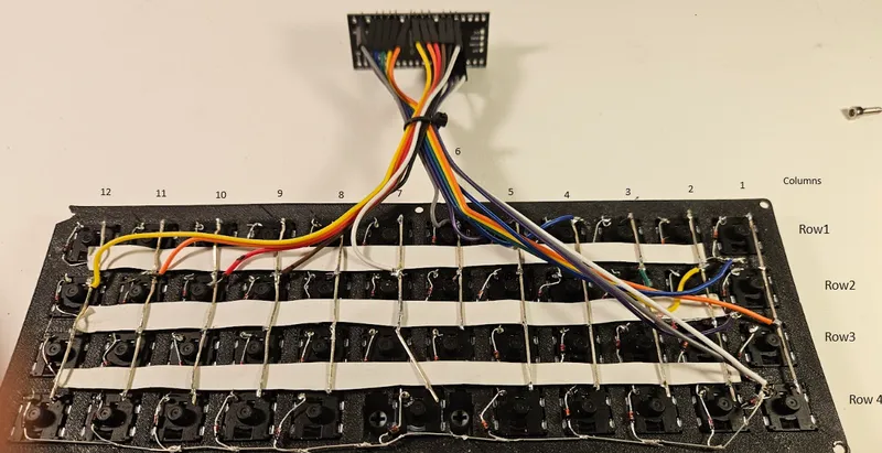 # Cols
keyboard.col_pins = (board.GP6, board.GP5, board.GP4, board.GP3, board.GP2, board.GP1, board.GP12, board.GP11, board.GP10, board.GP9, board.GP8, board.GP7)
# Rows
keyboard.row_pins = (board.GP21, board.GP20, board.GP19, board.GP18)
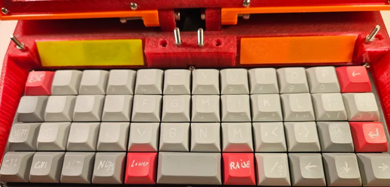
Keymap:
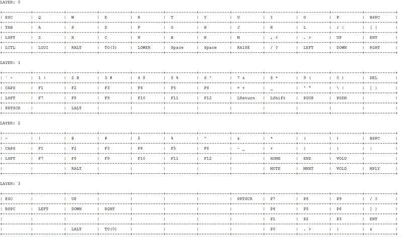
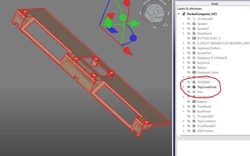
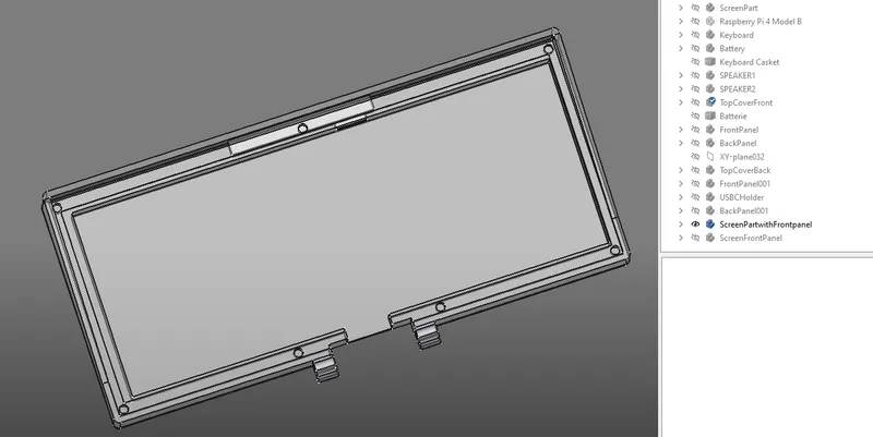
If you using the Keyboard you will need a different front Cover.
PCB Version:
PortablePi84_V27-TopCoverFront_KeyboardwithPCB
Handwired Version:
PortablePi84_V27-TopCoverFront_HandwiredKeyboard
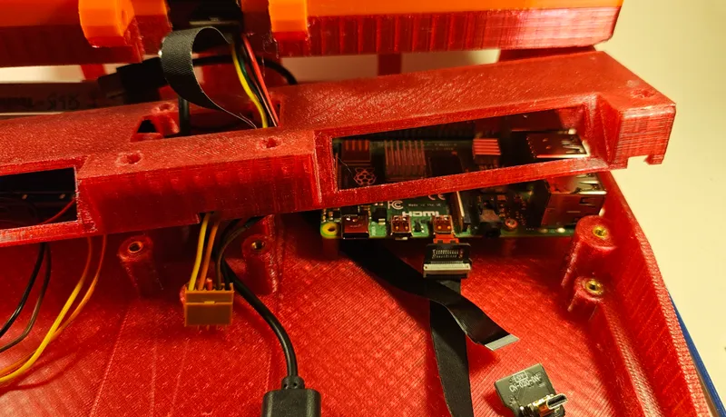
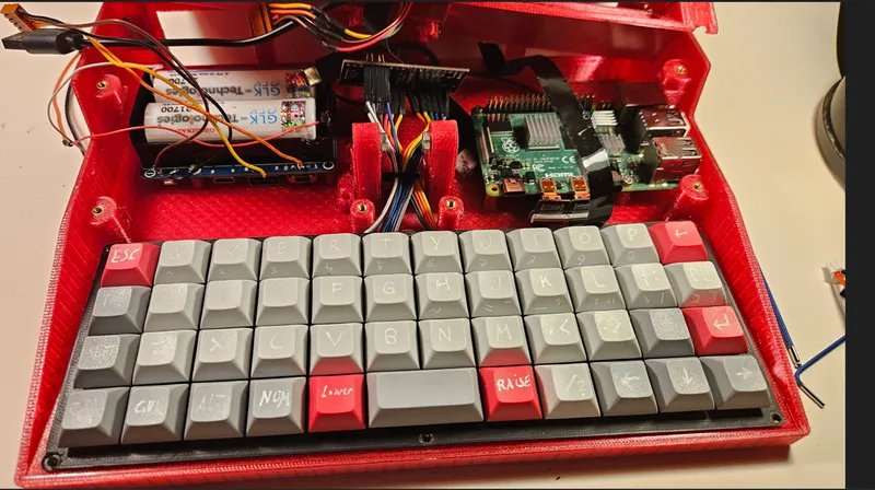
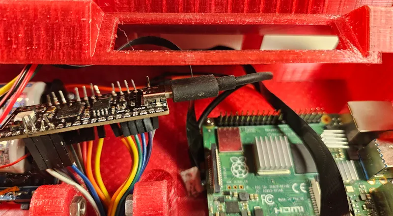
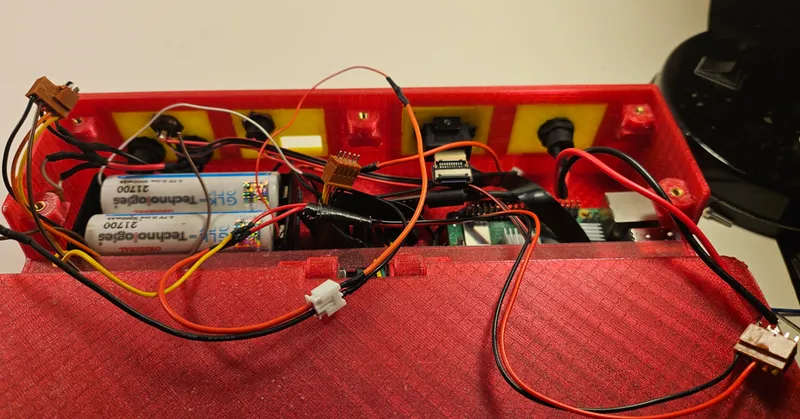
Internal cabling
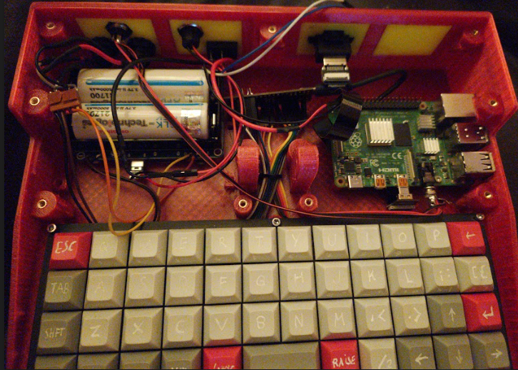
Symbolic Picture. Has changed already: No dupont cable for Pi power. See further down for more information.
You can see the handwired RP2040 tucked between the hinges.
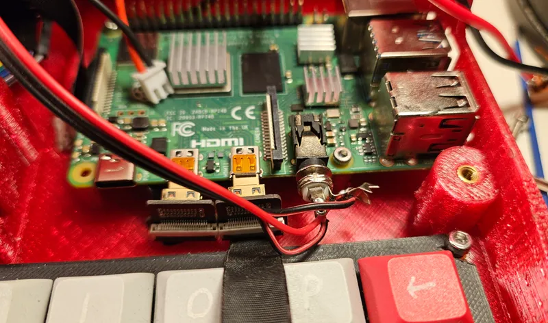
Internal USB Port (Keyboard)
The keyboard is wired internally to the Raspberry Pi on the undersite (not a nice job tbh). Therefore one USB Port is closed off.
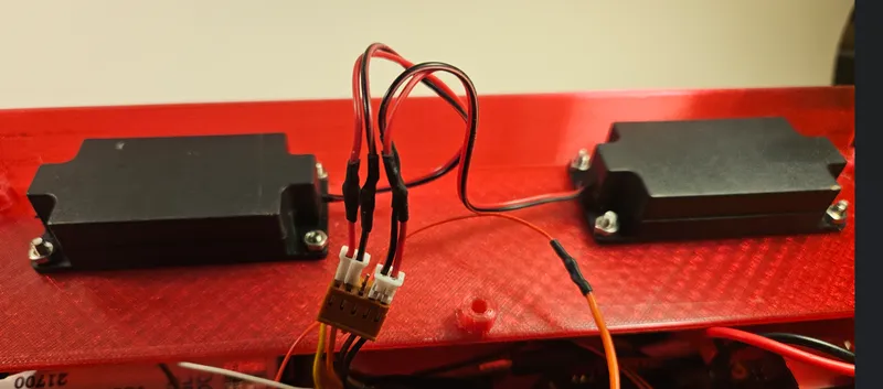
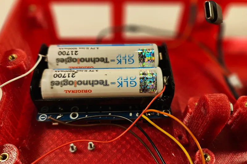
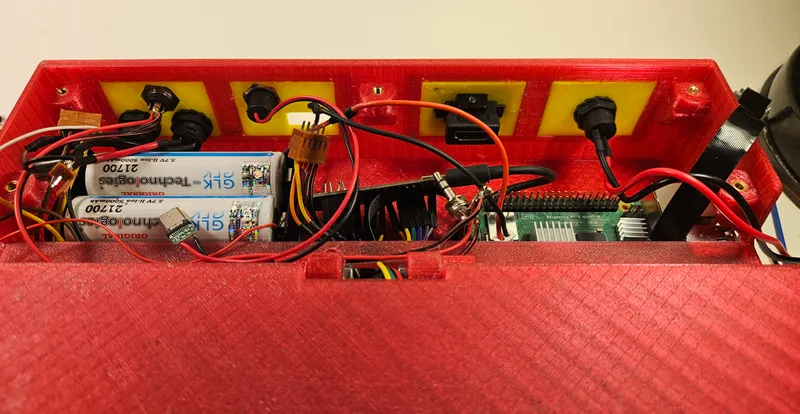
Battery cabling
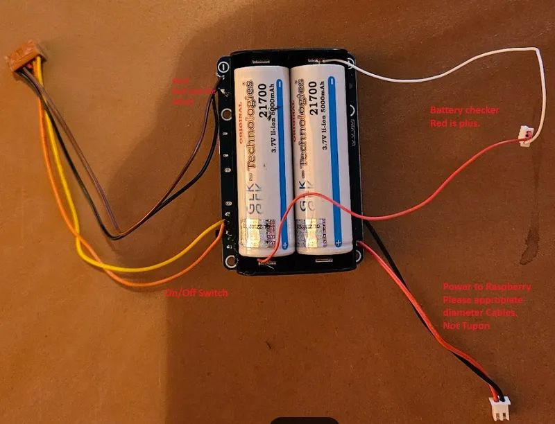
On/Off switch and Power is mandatory.
Battery checker connection is a Bonus.
I am not sure what boot should do.
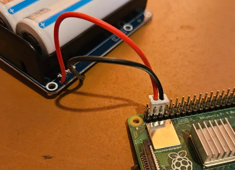
As you can see I have done connectors on every cable to make assembly and disassembly easier.
For the Power cable refer to part list. (I have used dupont but the Pi was rebooting)
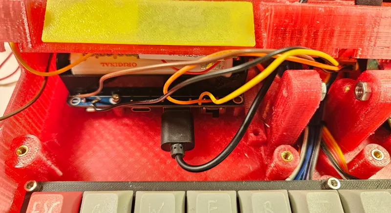
For more Clearance Underside. (Remark: On/Off must be off)
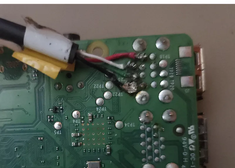
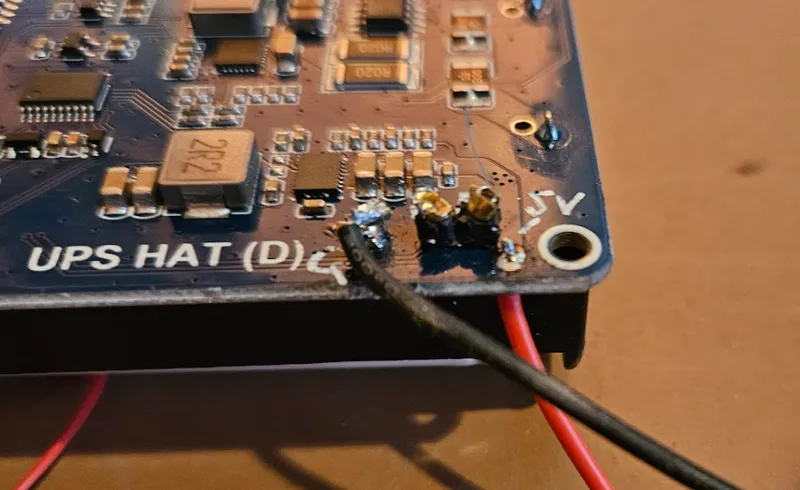
This battery hat have had pogo pins that I have had to remove. (Snipping it)
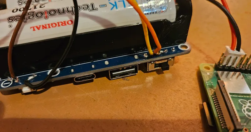
I was able to unsolder the 5V pogo pin. The other I was not able to, so i soldered directly on the remains. I was not able to use SDA/SCL connection successfully. (need more investigation)
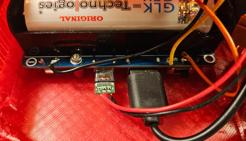
Power Connector fits fine on pinheader:(Please take care of minus and Plus!)
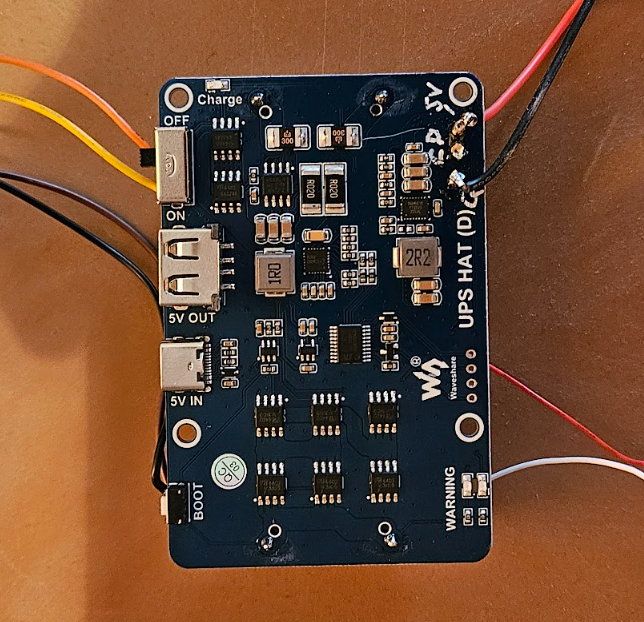
USB-C for charging.
USB-A is used for the Display.
On/off Switch Button is soldered in most left pin and middle. (not the mechanical solder part of the switch)
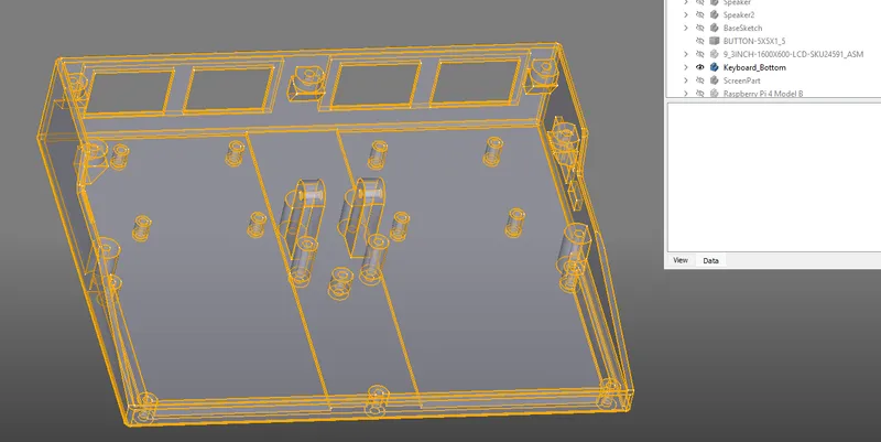
Assembly
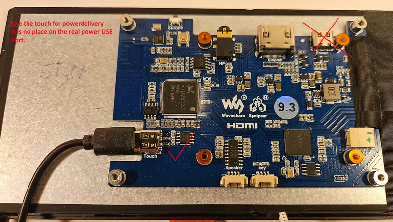
Screen:
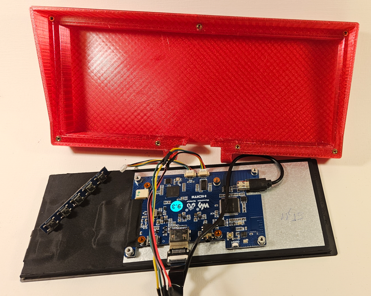
For Power delivery use touch input, else the display will not fit into the case.
Speaker Connection:
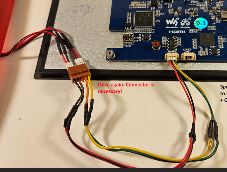
Connector type doesn't matter, but you will need it while assembly.
Screen Control:
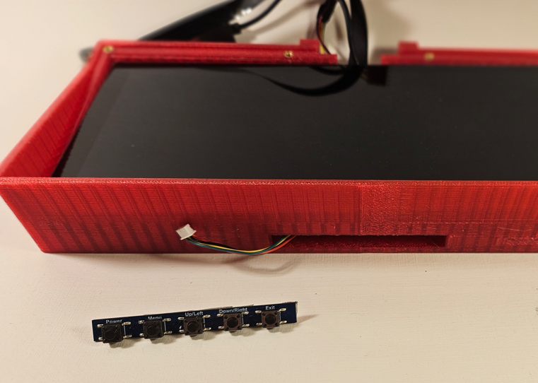
Use double sided tape to stick remote into the groove.
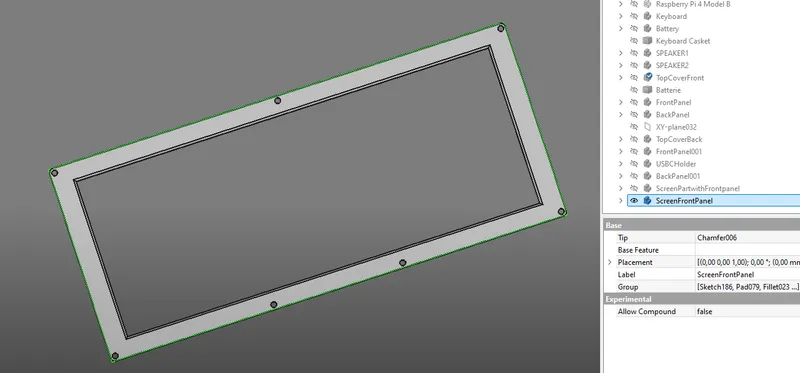
Front Bezel
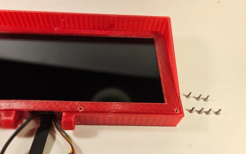
2.5 M Screews
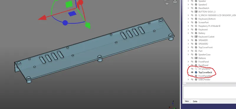
BackCover:
3 M screews and nuts. Glue nuts to speaker for easier assembly.
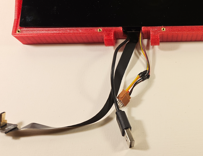
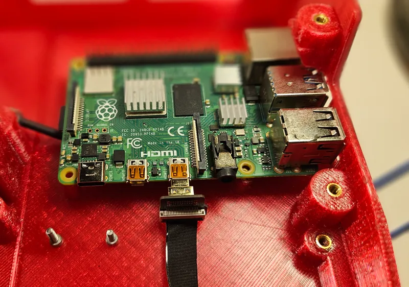
HDMI Cable preparation:
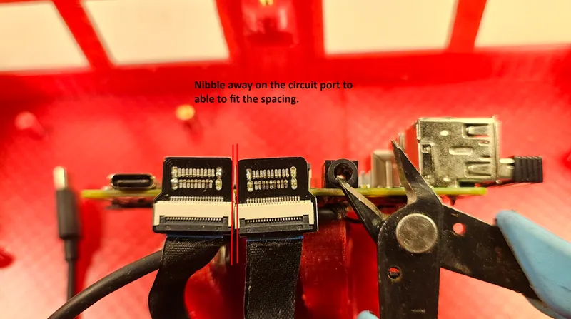
If you using 2 HDMI Ports you have to nibble away on the side of the connector to fit booth into the Pi 4.

Black site must always be top.
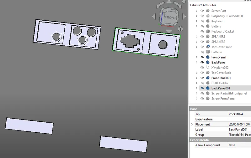
Frontpanel:
Use M2 screw's to connect Battery meter.
BackPanels:
Most of them Switches have a connector.
Pi:
Use 2.5 M screws. Route internal keyboard cable (next chapter) to the side.
Battery:
Use 2.5 M screws.
Add Top:
This is the hardest part. Route all the cables trough the hole in the fontcover. You have then to place the monitor on the back of the case. Route the hdmi cable without connector under the PI. I you have problems with assembly you may use the split front cover.

This covers you can add later after the screen is attached.

Connect HDMI Cable.
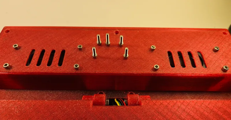
Keyboard:
Use M3 Screws. Place RP2040 between the hinges in the back.
Backpanels:
Insert back panels. It is a press fit.
Connect the Monitor Power to the Battery.
Connect usb-c power for charging.
Connect the internal port to the RP2040
Connect Audio extension Cable. (This is an old print, in the current version you have more place.
Frontpanel:
Screw down frontcover. Use 3 M screws.
Hinge:
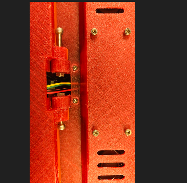
Use M4 screws for hinge. Glue again the nut to the top case makes live easier.
Finalize cabling:
Hope you have done enough connector.
Speaker:
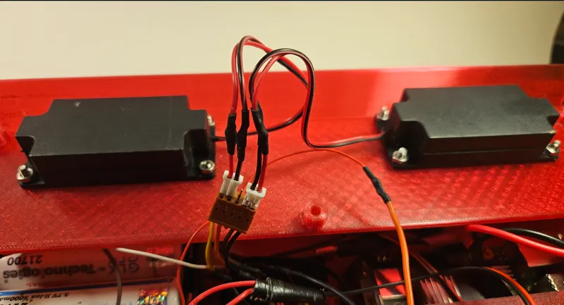
Connect Speaker cables. (inner cables are ground/-)
BackCover
Finalize the build with back cover. Use 3 M screws.
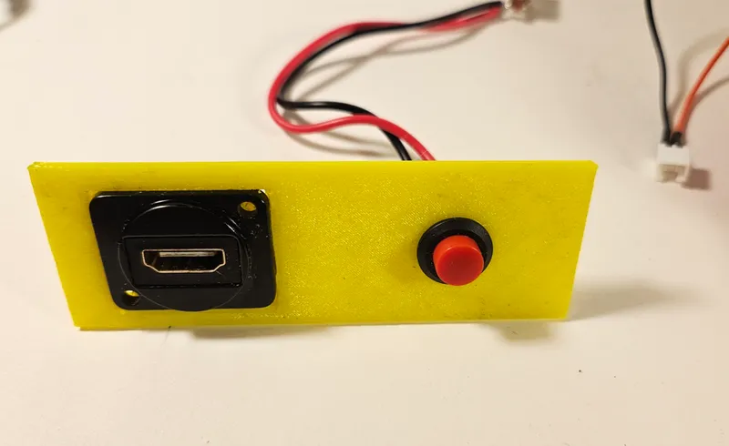
Interface Panels
For the interfaces in the front and the back you may design you own panels for your needs.
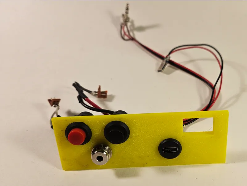
Example:
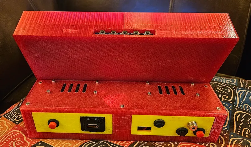
Red button connect to the battery boot button (Momentary)
Black button connect to the On/Off Switch of the battery (Switch)
Audio stereo Jack
USB C to load the Battery
Second HDMI out
Left red button Activate Battery Indicator (Switch)
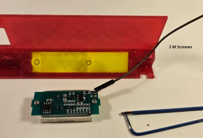
Battery Indicator
I using a led battery Indicator to check the power level of the battery.
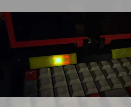
It is installed in the front panel. (2 M screws)
You press the Left red button to switch it on.
Parts for Build
All screws are 3 M except the Raspberry Pi / Battery and screen front panel. They are 2.5 m.
The hinge uses 4 M screws. It is helpful to clue the screws nuts to the hinge.
You will need threaded Inserts for this Project. A lot of them.
This are amazon affiliate links.
Tools:
Soldering Iron
Cables in different colors.
Cableconnector (Makes assembly and disassembly easier)
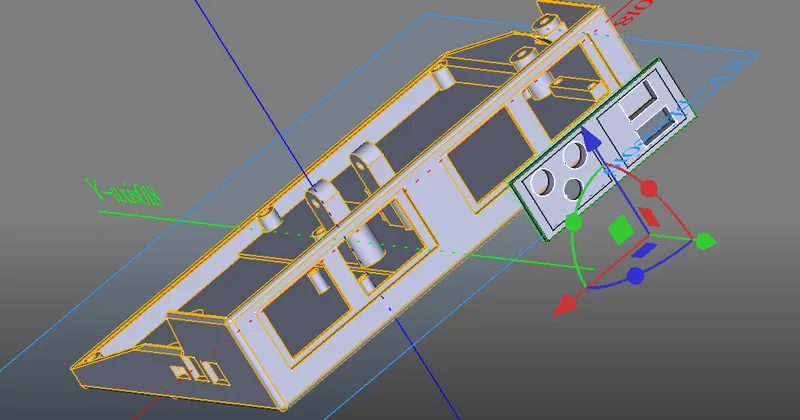
About Printing
For printing you will need support (tree/organic).
Positioning the parts should be obvious. ( Largest Plane down)
Sadly you will need a bigger Printer for the parts at least 300 mm X 300 mm.
Important: I have recognized that the hinge may break with to less infill. I use Prusa Slicer to increase the infill for the hinge:
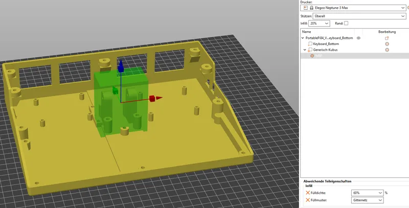
Main Parts are:
Screen Rotation for Raspberry Pi
To fit better the screen is rotated upside down. For the Desktop you can set it in the “Screen Configuration”.
For the console itself you have to set it in the
/boot/firmware/cmdline.txt
File: (One line!)
fbcon=rotate:2 video=HDMI-A-1:1600Mx600,rotate=180
Result should like as below:
console=serial0,115200 console=tty1 root=PARTUUID=309f1c16-02 rootfstype=ext4 fsck.repair=yes rootwait cfg80211.ieee80211_regdom=AT fbcon=rotate:2 video=HDMI-A-1:1600Mx600,rotate=180
Roadmap:
- Add lip to Screen Part to make a nicer close
- Find a better battery - done
- Make battery holder more modular - done
- Improve topcover so you have access to the innard without removing the screen - Done split frontpanel
- Make a Scad script for the panels – Done