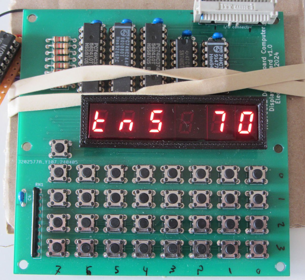
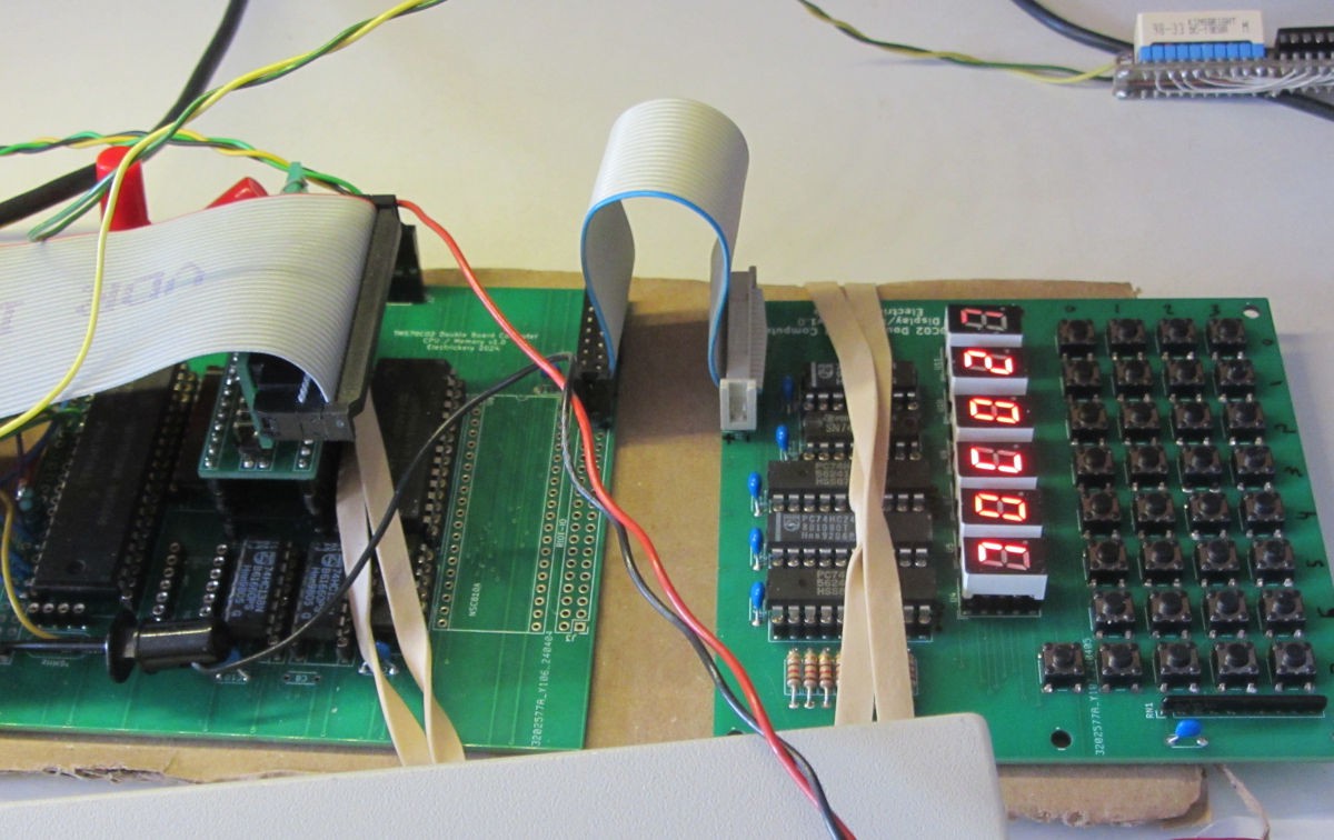
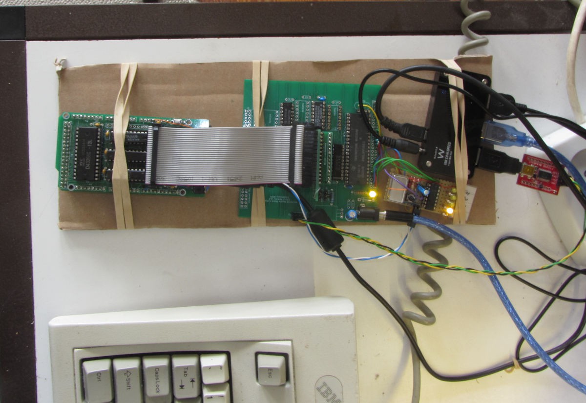
The T.I. TMS7000 line of micro controllers is an interesting architecture. These boards will provide a new platform to explore it.
To make the experience fit your profile, pick a username and tell us what interests you.
We found and based on your interests.
portBblinkSerialASL.lstThe simple demo-code demonstrating the board is working. It only blinks LEDs and outputs characters. It reads characters too.lst - 19.93 kB - 07/27/2024 at 08:39 |
|
|
TMS7000CPUMEM.kicad_sch_v1.02.pdfSchematic of the prototype board with most of the problems of the prototype solved. The NSC810A is still there, but it might be replaced bu a cheaper and more common I/O-chip, an MC6821, or 8255.Adobe Portable Document Format - 230.27 kB - 07/27/2024 at 08:35 |
|
|
The key scan is now working as it should, the key value to display pattern routine too. This startup pattern should scroll to show the remaining 'C02' characters of the message, but that is a ToDo item. Now functions should be assigned to the keys, at least for the values 0-F, memory, up, down, ... Most inspiration will probably come from the MikroKit09 and MPF-I.
The code is now more or less complete for now at version 0.3.2. The command naming might change and the Intel-Hex download isn't implemented yet. Here is the current help text, which summarized the command list:
** TMS70C02 Monitor Help Menu V0.3.2 ** Caaaa - Call subroutine at aaaa D[||+|-|aaaa[-bbbb]] - Dump memory from aaaa to bbbb E[e] - View/set echo Faaaa eeee dd - Fill memory from aaaa to eeee-1 with dd Gaaaa - jump to address aaaa Maaaa bb - Modify memory location H - Help menu Raaaa eeee - RAM test from aaaa to eeee Vssss eeee nnnn - Copy memory range ssss to eeee to nnnn *:ssaaaattdddddd....ddcc - receive Intel-hex record * = not yet implemented
See the complete code and resulting binaries (bin & hex) at the github site: https://github.com/electrickery/TMS70C02-Monitor
With support to both the Arduino firmware and the RomEmulatorTerminal script of a 'download-relay' it is possible to have a 'hands-off download' operation, where the target processor is held in RESET during download. For ROMs intended during startup, this makes firmware development almost as simple as the Arduino environment.
On the image are all relevant components strapped to a carton board and connected to a USB hub. The ROM-EMulator is conencted to the boot-ROM and the target board output is currently the serial port. Even the board is powered via USB. By bridging the RESET switch of the target board with the relay, the processor is halted until the ROM download is completed.
The Arduino sketch and download application script can be found are the ROM Emulator github project page: https://github.com/electrickery/ROM-emulator
Create an account to leave a comment. Already have an account? Log In.
Become a member to follow this project and never miss any updates