 Shrinath Nimare
I assembled the first board and it appears to work fine.
The main inductor is supposed to be a 10uH one, but its yet to arrive in mail so I have used a 1.5uH one for the time being. The intended PWM for the boost converter was 600KHz for the 10uH inductor, but for the 1.5uH one, I'm using 1MHz, straight from the MCU GPIO without a buffer or gate resistor :D
I have hence not made any power measurements either. The LED does seem to heat up at 70% duty cycle, so does the FET, but anything lower than that, and I do not see any heating. The LED is dissipating maybe a few watts, but definitely not a lot.
Interestingly, I was seeing a lot of ringing on the FET gate but it disappeared when the duty cycle was increased.

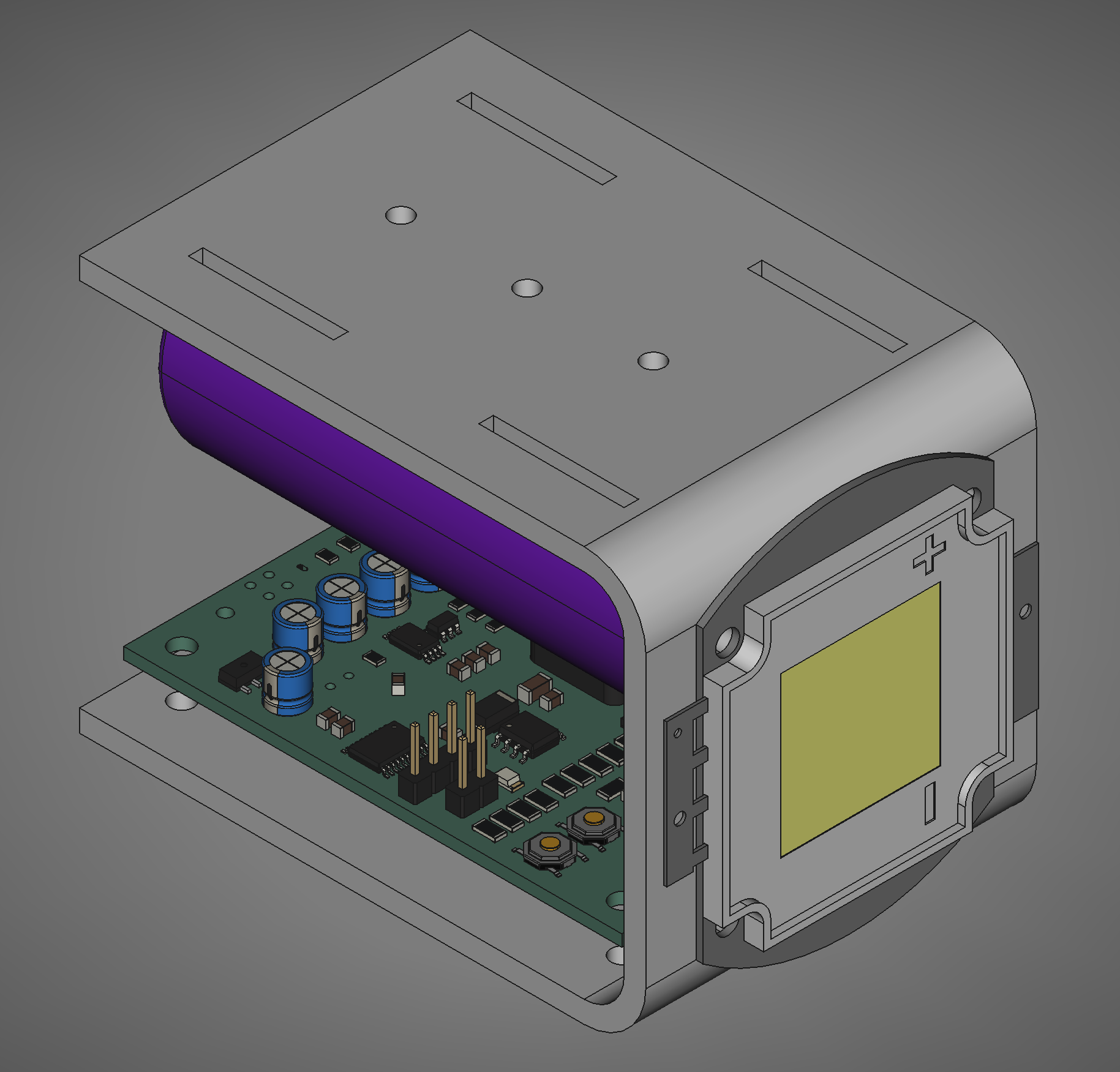
This was supposed to look like this but the company doing the sheet metal laser cutting refused to do the bending, and I discovered 3mm aluminum is a lot more stiffer than I expected and could not be bent by hand (yes I actually thought 3mm aluminum could be bent by hand)
Besides this, the circuit has no current feedback which is important for driving LEDs. I'll probably include it in the second version.
Discussions
Become a Hackaday.io Member
Create an account to leave a comment. Already have an account? Log In.