 schuyler4
It is now possible to use normal trigger with multiple channels with the resulting waveforms synchronized. However, this feature is experimental; there are a lot of bugs and problems still.
The two oscilloscopes are synchronized by passing the trigger output from one scope to the trigger input of the next scope. This is shown in the picture below
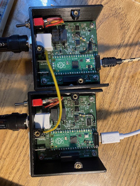
Currently, trigger input and output are just headers on the board, but the plan is for them to eventually be SMA connectors or similar mounted on the back of the scope.
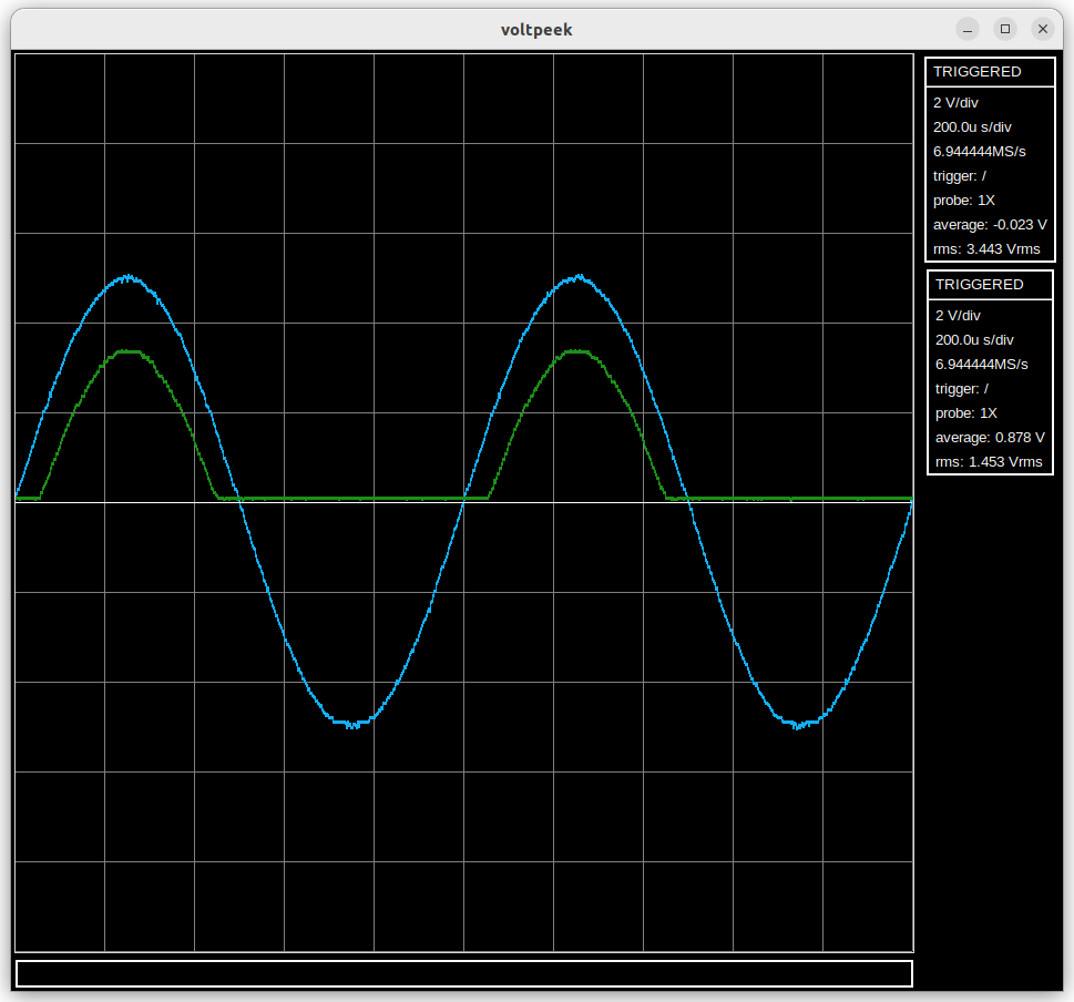
Using these two channels it was possible to capture the following waveform (input and output of a half wave rectifier).
Problems and Future Work:
1) Better identification of scopes. There must be a master scope which actually triggers on a waveform and triggers other connected scopes. Currently it is very difficult to figure out which scope this is. To fix this each scope will have to store its own serial number which voltpeek can then read and display.
2) Trigger jitter between channels. It is possible to correct trigger jitter from one channel in software and apply the same correction to the other channel, but when trigger jitter is uncorrelated channel to channel, it becomes a problem again. This is noticeable on very low time scales.
3) Various bugs related to freezing and the waveforms not being displaced correctly.
4) Add synchronization for auto trigger. This will require new PIO code.
Discussions
Become a Hackaday.io Member
Create an account to leave a comment. Already have an account? Log In.