Arnov Sharma
DESIGN

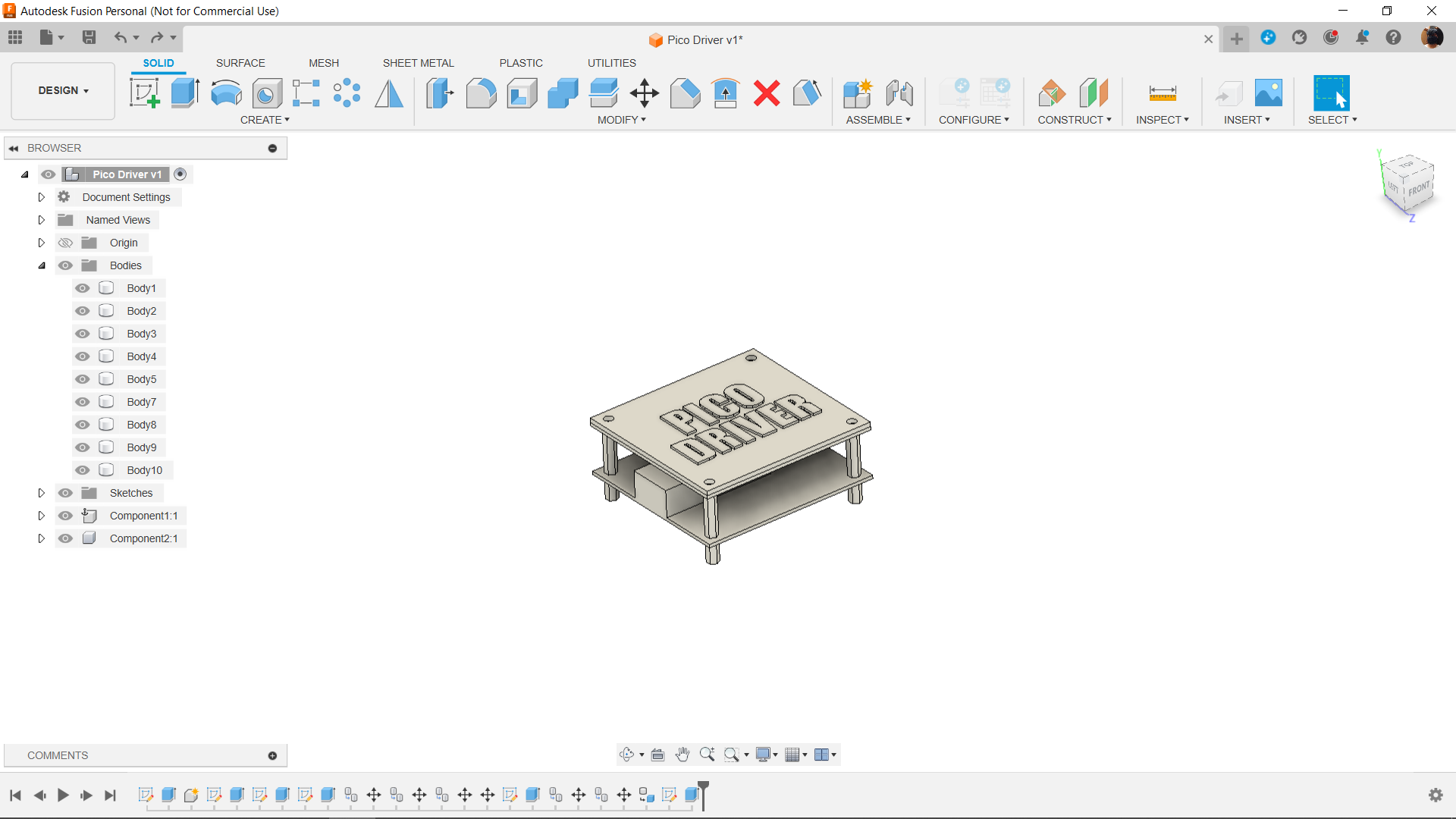

We first prepared the design in Fusion 360, which included a board for the Raspberry Pi Pico and additional parts like a barrel jack and CON2 for attaching the load.
Here, we use PCB standoffs which connects to the main board and we then place another board on top of main PCB which will act as a cover.
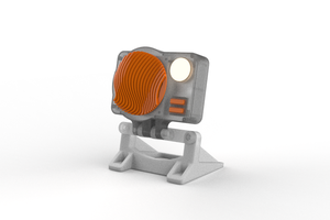
We then built a third customized layer, or board, that will be 3D printed, and on top of it we extruded the PICO DRIVER initials.
After completing the design, we exported the third layer file into a mesh file and 3D Printed it using dual color PLA, black for base layer and White for Top initials layer.
PCB DESIGN


Following the model's completion, we created the project's schematic, which was divided into three main sections: the input section, the Pico Setup, and the Mosfet switch setup.
The input section comprised of an AMS1117 3.3V Voltage Resulator input connected in series with two diodes and a DC barrel jack whose positive was connected. We have added a 10uF 50V 1206 capacitor to the AMS1117's input side and a 1uF 50V 1206 capacitor to its output side.
There's also an LED connected with a resistor in series linked to the positive of DC jack before diode; this LED will act as a power indicator.
Next comes the Pico Section, where the AMS1117's output terminal is linked to 3V, and GND is connected to GND. The AO3400 Mosfet's gate is wired to Pico's GPIO0.
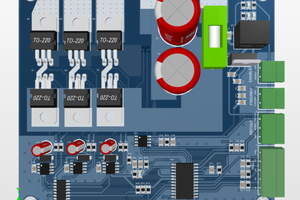
Two mosfets are utilized in the mosfet switch arrangement because the IRFZ44N is a high current, high voltage mosfet with a gate-source voltage of 12V to 20V. Because our pico GPIO can only output voltages lower than 3V, this is insufficient to completely turn on the mosfet.
In order to address this issue, we added an additional mosfet, the AO3400, and wired its source to the IRFZ44N Mosfet's gate and drain to 12V. In this case, the gate-source voltage of the AO3400 is less than 4.5V, which is ideal for The PICO.
Once the schematic is finished, we create the board shape and mounting holes using the dimensions from the Cad file.
HQ NextPCB Service
After completing the PCB design, we export the Gerber data and send it to HQ NextPCB for samples.
We placed an order for a white silkscreen LED board.
After placing the order, the PCBs were received within a week, and the PCB quality was pretty great.
HQ NextPCB and HQ Online are the overseas trading brands of Shenzhen Huaqiu Electronics Co. Ltd.. Huaqiu has served national engineers for over 15 years, becoming a household name in providing full-feature multilayer PCBs engineers can trust.
NextPCB brings these capabilities, speed, affordability and more, to international customers, skipping the middleman and providing the same intelligent online quotation system from the industry’s experts.
Huaqiu Electronics believe innovation is key to maintaining excellence, which has motivated them to transform the electronics manufacturing industry. Huaqiu’s in-house engineers developed the free Design for Manufacturing software, HQDFM, revolutionizing how PCB designers visualize and verify their designs.
HQDFM: Free Online Gerber Viewer and DFM Analysis Tool
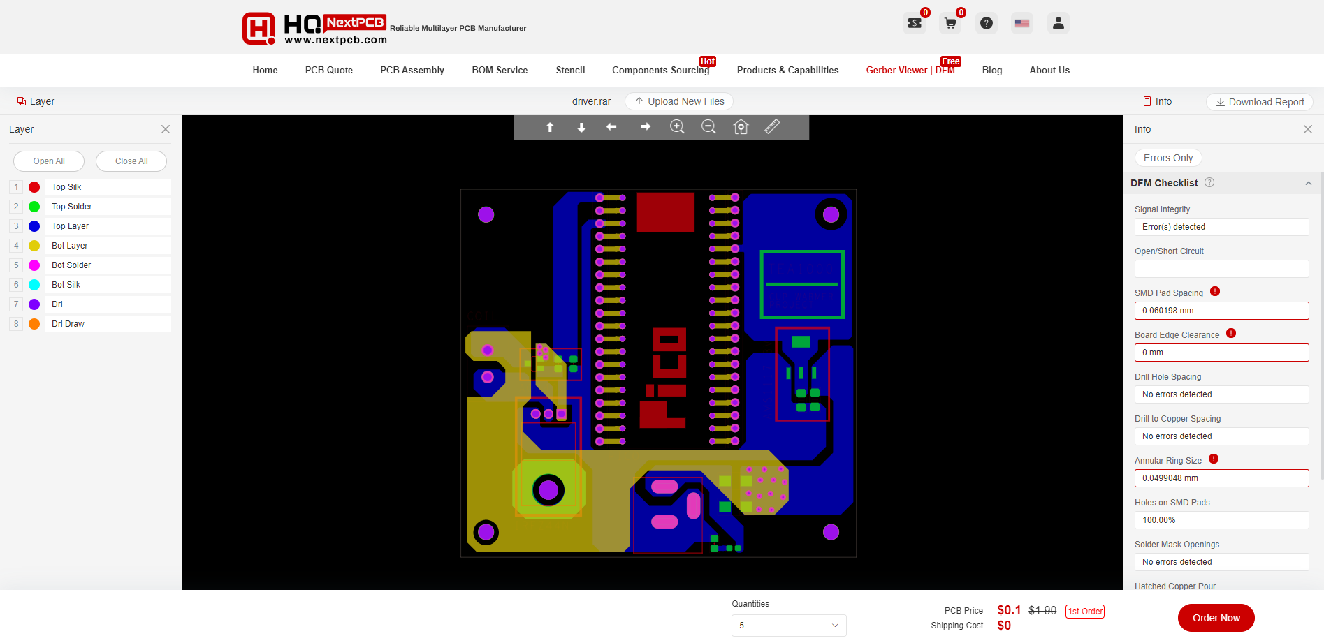
Also, NextPCB has its own Gerber Viewer and DFM analysis software.
Your designs are improved by their HQDFM software (DFM) services. Since I find it annoying to have to wait around for DFM reports from manufacturers, HQDFM is the most efficient method for performing a pre-event self-check.
https://www.nextpcb.com/free-online-gerber-viewer.html
With comprehensive Design for Manufacture (DFM) analysis features, HQDFM Gerber Viewer is a free, sophisticated online PCB Gerber file viewer.
Along with supporting the top 5 web browsers, it is compatible with RS-274x and Extended (X2) Gerber files as well as OBD++ files from popular PCB CAD programs including Autodesk Eagle, DipTrace, DesignSpark, Altium Designer, and KiCad. HQDFM is a product of HQ Electronics, which also developed...
Read more »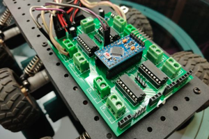
 Jithin Sanal