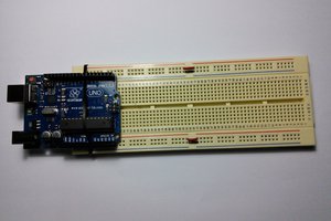
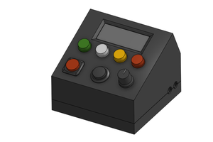
This is blinking an LED with an Arduino - advanced edition.
The details are for the Attiny2313, but you can use whatever you want, you can replace the display with whatever you want or just remove it altogether
(note that I do not run the Attiny at CLK/8 - uncheck that box or it'll be slow)
I know the Atmel 8 bit family has hardware PWM, but I wanted to keep it simple and not read the friendly manual again.
So I set up a loop that counts from 0 to 255 in an endless loop.
If the loop counter exceeds a brightness value (which also goes from 0 to 255, but in a programmed, exciting fashion), it switches one LED off and the other on.
This way you get two cross-fading channels of PWM with 8 bits of granularity and full control.
The LEDs are connected to PortA0 and PortA1 (pins 4 and 5).
Now you need a button for each player to press. These go to INT0 and INT1 (pins 6 and 7). These are also set up as ISRs.
And that's where I hit the first snag - My Hello World just added the direction variable to the brightness variable once every 16 passes of the loop mentioned above. But pushing the buttons did not change the direction of the ball, ahem, the way the colors faded. Long story short, I never write the direction variable in the main() and I never read it in the ISRs. Compiler optimization got the better of me and took several hours (and a night's sleep) to figure out. The solution was to declare all variables volatile. (and take a look at the generated assembly listing from time to time)
Next I added the score display. Young me, interested in electronics especially if it contained LEDs and/or looked unusual, but with no knowledge past relays, bought it a quarter century ago. It's 3½ digits and I haven't found a use for it. Until now.
Remember PONG (the real one)? The score only goes to 15, because it's a 4 bit machine. And since I wanted several difficulty settings, I use the tens digit for that so each and every LED in this display gets a chance to light up.
The score display is BUSsed internally, so all segments are connected together, very disappointing for young me as I couldn't make it spell anything back then.
Since we have enough I/O this time, no need for a support chip (but hint hint, if you need to strobe up to 10 digits, consider using the CD4017, it only needs two inputs)
So I set up TIMER0 to do the strobing. I implemented it as a state machine. Depending on the internal count, it enables PortD0, PortD1, PortD4, PortD5 (since D2 and D3 are hardware interrupts). And depending on which port it enables, a different digit lights up and different actions have to be taken.
There is a sevensegment[] Look Up Table that encodes the outputs for PortB. Note that PortB3 can't be used as this is going to be set up as a buzzer output to give you those beeps and boops of yore. The LUT can be fed a number from 0 to 9 and it translates it to the outputs needed to make a 7-digit display light up that number. Also, it adds a 'd' to announce difficulty setting. You can add many more letters and symbols as you please.
So next I set up sound. I had that in TinyPONG from I think 2009... I'm collecting vintage video game consoles, now one that I made can almost be considered vintage... so I just stole the routine. timer1_init() sets it up and
OCR1A= 600; //frequency
TCCR1A |= (1 << COM1A0); //sound on
_delay_ms(50); //how long you want to beep
TCCR1A=0; //sound off
makes a Beep. Advantage - no CPU time (I eventually replaced delays with a countdown that triggers in the main loop and turns sound off when it reaches 0). Disadvantage: You're tied to a certain pin and can't use that for other stuff.

 treibair
 mircemk
 Luis A. Tórtola