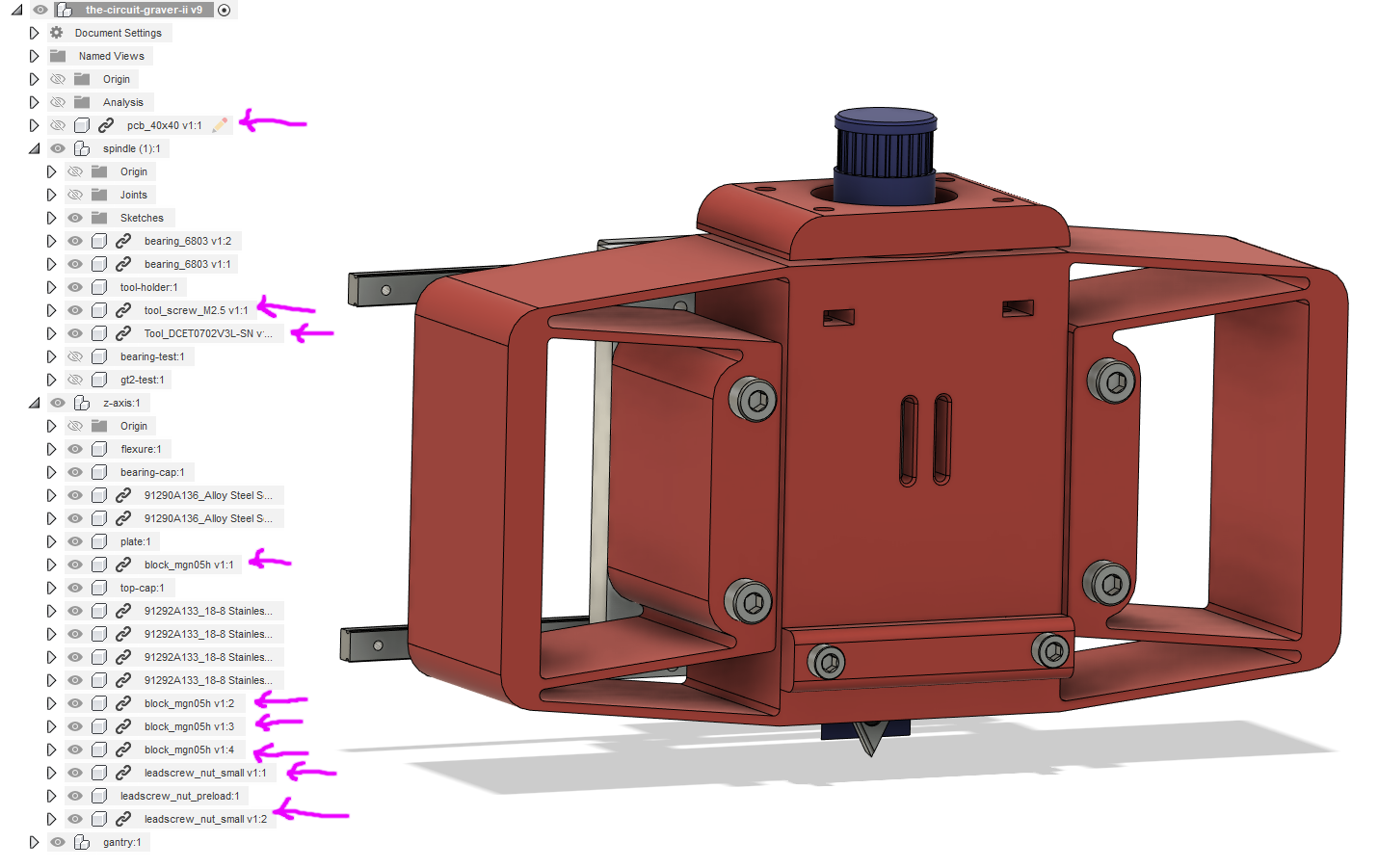
A clean sheet redesign! A new CAD model! To be fair, I carried over a lot of parts from the first iteration, highlighted on the screenshot here, but all of the 3D printed bits are fresh:
The back uses the preload mechanism I focused on last time, adding a flexure to account for lead screw Z-axis translation offsets. Note that the entire preload nut is lifted off its mounting plate by 1.5 mm so it hangs out in mid air:
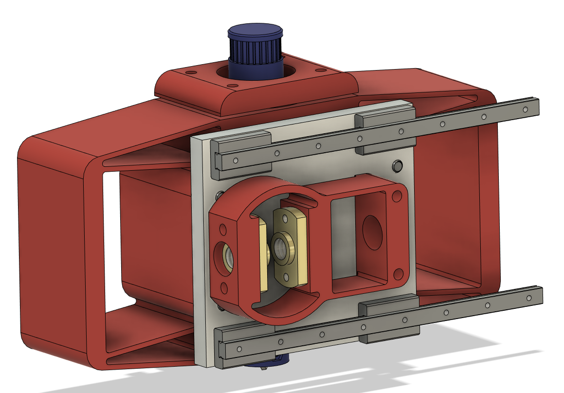
And! A plate! Yes, that lighter grey part is a 6.35 mm (1/4", I guess) aluminum plate which I intend to get cut and tapped to order. I found one popular online vendor that can do it in a week for around $25, and it's nice to not have to really worry about stiffness on that part. This example is a great argument for access to a waterjet cutter (and, ideally, a tapping arm), but those lovely machines are expensive to both buy and operate. Eventually, the plate will extend up a bit to support the Z-axis servo, the R-axis stepper, and the pressure adjustment mechanism. I think it will still be in the $30-40 range which is very worth it. Not really shown here are locating posts that align the Z-axis flexure and lead screw nut flexure during assembly and bolt-tightening.
Also as discussed previously, I bumped up to 6803 bearings and added a split bearing cap to help with assembly and reduced concentricity issues caused by non-ideal print orientation:
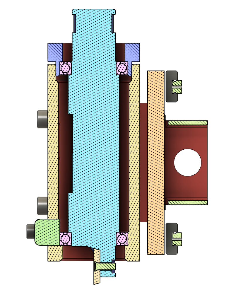
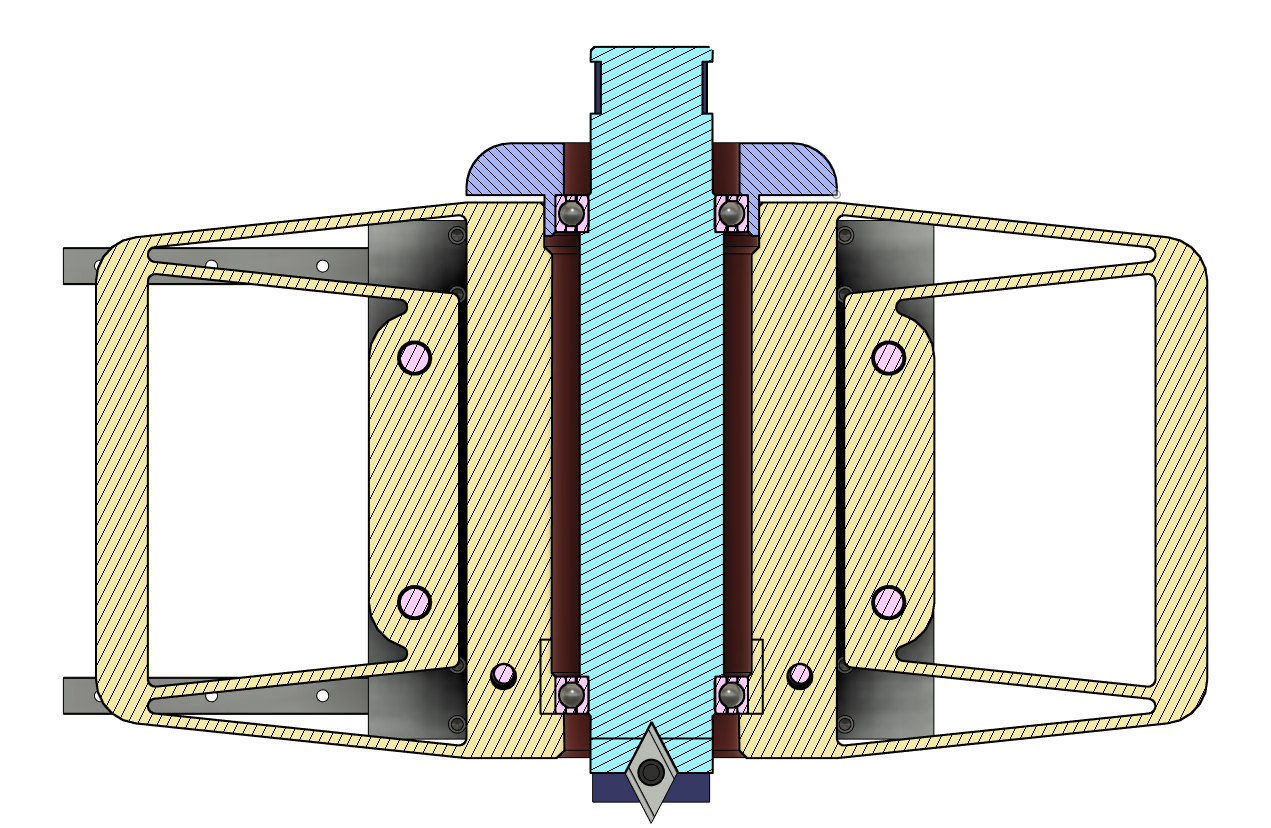
The spindle is preloaded by the top cap, probably with Belleville washers or something. Many little details here, like ease-of-assembly chamfers, the GT2 belt pulley cut into the top of the spindle, the flat part on the spindle to hold a label (or black marker scribbles) to make rotation obvious, etc. Including the first iteration a few weeks ago this is the third preloaded rotating thing I've designed; after perhaps 15 minutes of hand work (mostly sanding the cap a tiny bit to improve fitment) it came together nicely:
I let the ~5 hour print of all the parts run over night, noting that in my sleepiness I printed the spindle in the incorrect previous orientation. In the morning, I chopped the knob off the top and printed it tool-up, then assembled the mechanism to the printed plate:
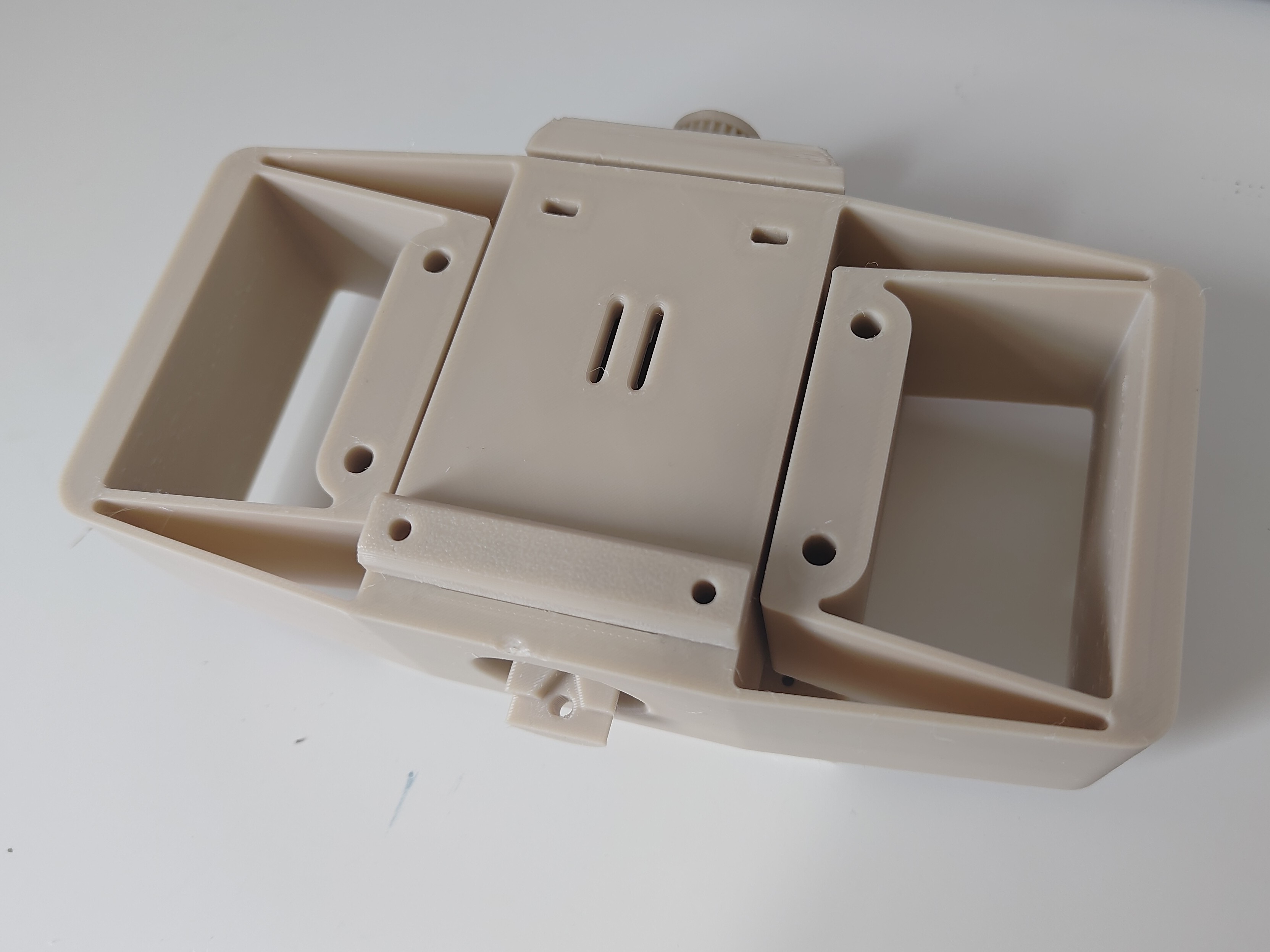
It feels really solid. The spindle rotation isn't as smooth as it could be, but I'm attributing this to a bit too much bearing assembly force before I'd really gotten all the hand-fitting done. The flexure movement is stiff where I'd like it to be, but seems very servo-actuate-able. The cutter is super rigid and I can't detect any off-axis movement by hand, which is about as qualitative as metrology gets, I suppose.
This was all helped by a few quick test prints during the design process, prepared in the model print orientation:
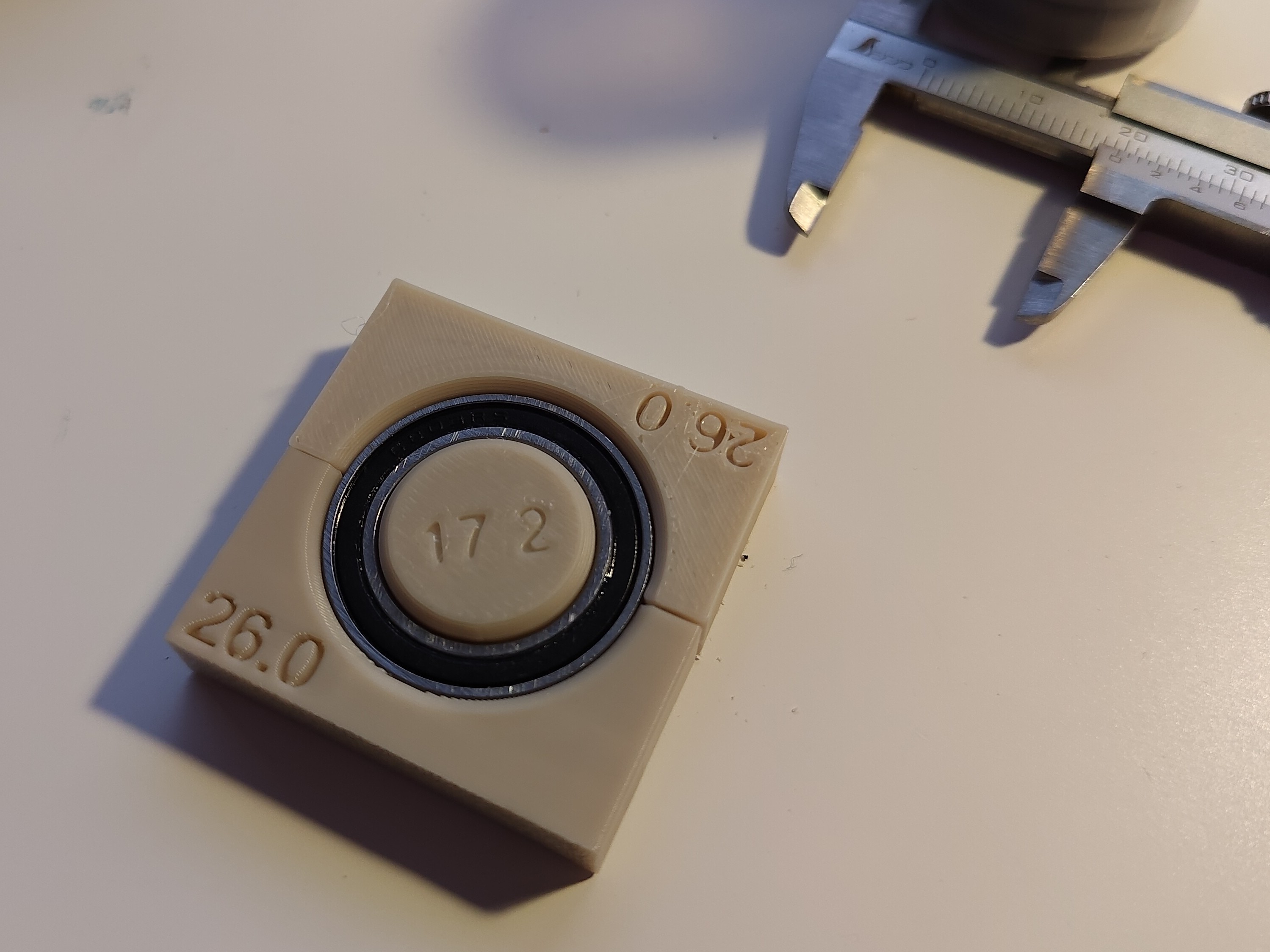
I'm stoked about the results of this design session; with any luck I can get through a full spiral of the machine (as in, all the way out to cutting a real circuit!) without needing to start over again. Next, I'm going to sort through the Z and R axis actuators to wrap up those two degrees of freedom, and then start working on the gantry, remaining X-axis things, and overall machine frame. I'm going to give heavy preference to reusing X-axis parts when I get to the Y-axis, so with any luck that bit will go relatively quickly and machine design will accelerate from here. Even though the aluminum plate is a lovely way to throw material at stiffness concerns, I'm hoping to minimize further use of commercially fabricated parts; the test rig, after all, seemed to do fine as a fully 3D printed assembly, and it makes iteration speed oh-so-much-faster.
 zakqwy
Discussions
Become a Hackaday.io Member
Create an account to leave a comment. Already have an account? Log In.