Titles like "Machine Design Part x" sitting next to other machine design log updates probably aren't useful. I may go back and edit them at some point! For now, progress:
 Motor mounts! Mirroring! A front plate! Lots to consider here, mostly that I'm in a hurry and want to do a full loop test this weekend. Given time and materials other than FFF 3D printed parts (as in, another aluminum plate, etc), I might have made the whole base square; but most of the stuff is in the back, and the motors should be fine hanging on brackets for now. Famous last words! I like the tripod base, as it reminds me of the similarly-sized microtome from ~100 years ago that sits on my desk. The two NEMA 17 steppers that drive the lead screws are a bit outside the triangle, but they should balance each other reasonably well, etc. This design pushes what is reasonable to consider without any FEA or pen-and-paper analysis, I suppose, but I'm hoping everything is just way stiffer than it needs to be at this point. Things like using the Y-axis rail mount as the main structural member that spans the feet, which itself is just a copy of the gantry, probably isn't great design practice. Ah well, that's why we'll test soon!
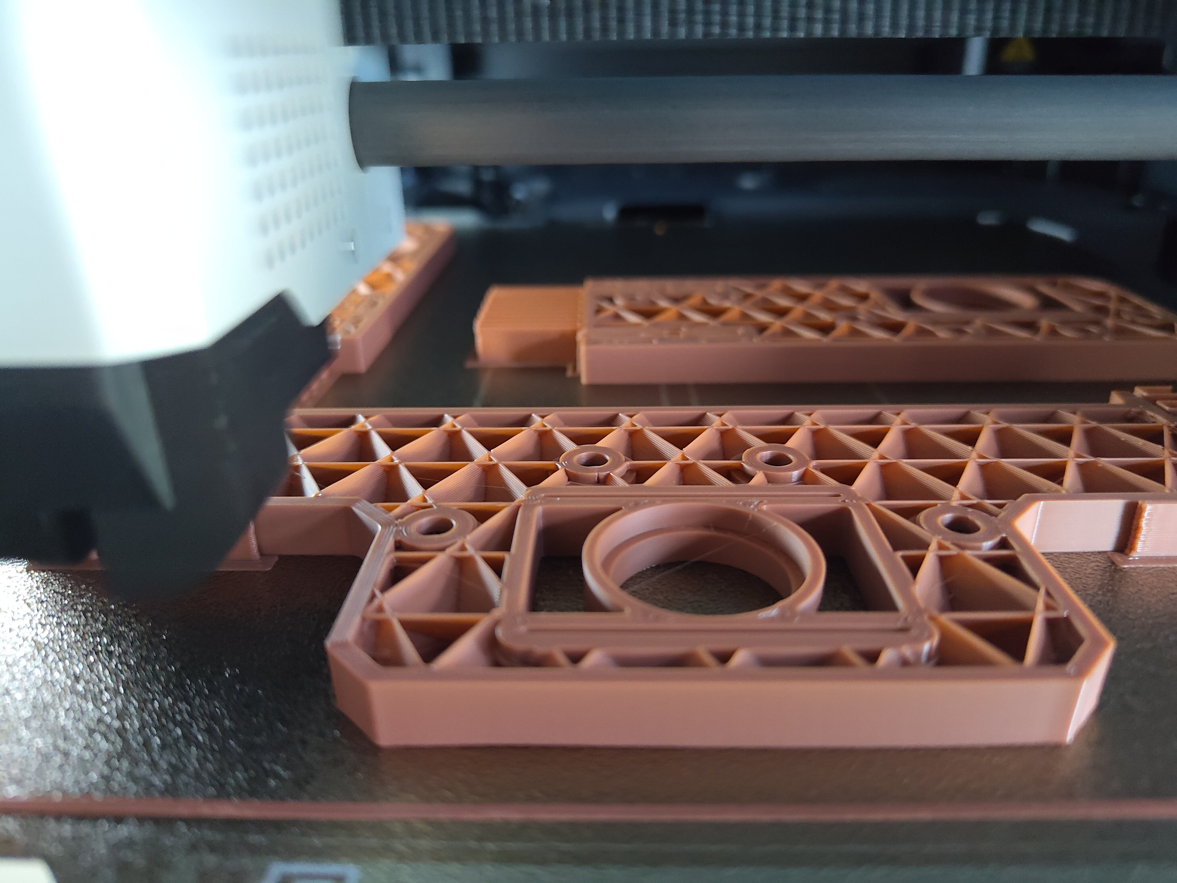
 The back plate and two gantry legs are printing now:

... and should be done early enough to test fit and start printing the base, front plate, and motor mount overnight. Then tomorrow I can print the Y-axis bits (which are a different color!) and start assembling! I think removing the Z-axis assembly and testing the rest for alignment will be the right move.
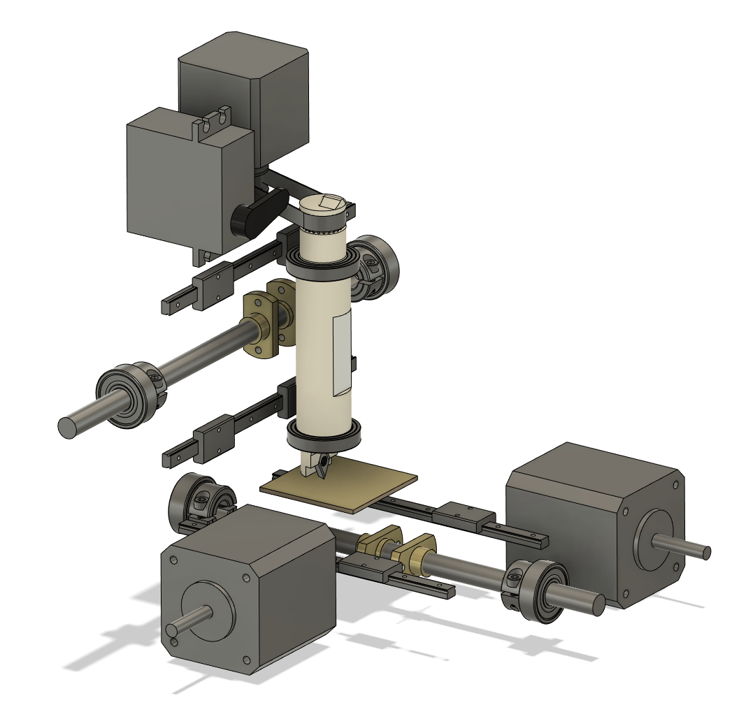
While I wait, I turned off all of the structural parts (3D printed bits plus the laser-cut aluminum plate) other than the spindle and took a screenshot of the CAD model; this is a good guide to the whereabouts of the various axis constraint and drive mechanisms:

 zakqwy
Discussions
Become a Hackaday.io Member
Create an account to leave a comment. Already have an account? Log In.