 FoxHood
The old approach was messy, based on flawed ideas like a 9V being a good choice and no way to automatically conserve energy. So, time to bring it up a notch.
I originally considered a back-up capacitor/battery that can power logic while the leds only turn on when USB is plugged in, but with consumption expected to be around 7mA and the experience I’ve built up dealing with them: I’m opting for a Li-Ion cell instead than can power the entire clock for a while.
Depending on the cell chosen it should be possible to power the clock for anywhere from ~4 days with a small 800mAh Pouch/14500 cell to ~18 days with a 3000mAh 18650 cell.
Primer:
Lithium-Ion batteries are a double-edged blade. They store significant amounts of energy, but this also renders them a little bit volatile. As in they can turn into an incendiary device if badly treated. The short list of rules are:
- Do not let them overcharge (4.25v>)
- Do not let them discharge too deeply (<3V)
- Do not overload them beyond their ratings (depends on cell)
Bit intimidating, but not that hard once you figure out how to manage power effectively. In this project I went for a three layered approach to handling power: Charger, Protection and Power-Saving.
Charger:
A good charging IC can handle safely charging the battery, avoid overcharging it, provide protection to the charger’s power-source and power the load.
I went for a TI BQ21040 charger in this implementation. I like this little charger as it is surprisingly flexible. It is designed largely for small electronics that need to be powered while charging or having its battery removed/swapped. If a NTC/Pull-down resistor is present the charger behaves like a regular charger with safety features such as a low-current threshold and Timers. But without a NTC/Resistor it enters a “Timer Termination Disable Mode” and just acts as a dumb 4.2V regulator. This is nice for projects like this as one can just ditch using a Li-Ion cell if they don’t want to use that.
Current limit is set to ~450mA with termination threshold being 1/10th of that (45mA). This should keep the device well within the limits of even a USB 2.0 data port (max 5V/500mA). Going to also use a NTC for monitoring battery temp just in-case.
Battery Protection:
At too low voltage the device should shut-down as much as it possibly can to prevent the battery from discharging any further. For this I went for an MCP65R41T-1202 3uA Comparator with built-in Voltage reference that controls a cheap little SY6280 Current limiting load switch. If voltage drops below ~3V the comparator shuts down the load switch, reducing the power consumption of the device to <7uA when taking in account the Comparator(3uA), resistor divider(2uA), off-state switch(1uA) and the leakage of the charger IC(1uA). This would take almost a week to drain 1mAh of charge at this point.
The current limiting ability of the load switch should also protect the cell from short-circuits past the switch.
Power Saving:
Complete shut-down should be the last resort. Before that a grace period of trying to preserve power while still letting the clock keep ticking would be nice. The simplest way to do so is by turning off the Leds once the battery voltage starts to drop below 3.5V which one can assume equals nearing end of charge. As the leds make up for crudely 95% of power consumption.
Idea is to use the same comparator as for the battery protection, but set to trigger at <3.5V and turning off a run of the mill BSS128 NFET.
Final set-up diagram:
Chaining all the blocks together this is the resulting diagram:
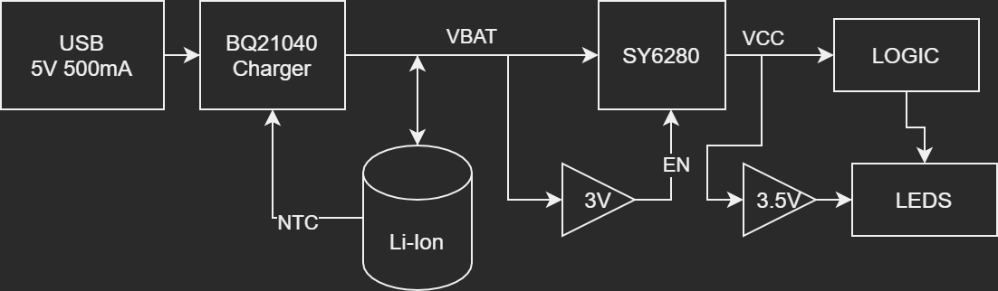
A bit of a chain and arguably took more work than the actual BCD logic. But should be a decent solution for this project. Not super refined, but good enough for a single PCB BCD clock.
Discussions
Become a Hackaday.io Member
Create an account to leave a comment. Already have an account? Log In.