 FoxHood
First stop is a dissection of my original and the many failures as the creation of a teenager who just saw a couple of schematics and bashed them together for a clock.
After all this time. Still working. These old CMOS ICs are seemingly immortal. Same can't be said for stuff like the switches. They got rusty/dirty and will simply NOT stop bouncing. Like i had better result setting time by just poking at the contacts with a jumper wire....
Electronics:
Logic consisted out of a set of CD4000 ICs:
- 1x 4060 outputting 2Hz from a 32khz clock crystal
- 1x 4013 that was halving the 2hz into 1hz
- 3x 4024 7-bit Binary counters
- 2x 4082 Dual 4-input AND gates for hitting the CLK and MSR pins on hitting 60 on (3 were used)
Inputs consisted of:
- 2x tactile switches for advancing Minutes and Hours
- 1x Dual DIP switch for enabling CLK from 4013 to 4024 and turning off the leds via the NPN
- 1x Jumper for switching between Power going through 2 Diodes or the 7805.
Output:
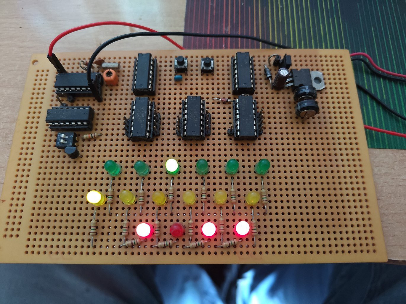
- 16x Leds for indicating time in Binary.
Power:
- a 9V Battery Clip acted as the input
- A pair of diodes OR a 7805 acted as a voltage drop
- A 10uF can along with a pair of small super-caps handled smoothing and backup in-case of disconnect.
Problems:
1) 4013 is redundant
while it seems logical on paper to divide the 2hz into 1hz. The exact same effect could have been achieved by just shifting the output of the first binary counter by one bit. As in binary theory: every bit essentially counts half as fast as the previous.
2) CD4000 is underpowered/overloaded
I didn't really knew how to read Datasheets at the time, so i never really looked at what the CD4000 could use and how much they could drive.
Turns out these were designed to be powered by up to ~18V and while they can work with just a few volt, their ability to drive plummets to just a few milliamps. Measuring the voltages show that the 4024 outputs were getting pulled down to 3V, indicating that they were being overloaded by the leds
3) The Leds SUCK
Speaking of leds. These old 5mm leds with coloured plastic domes diffusers are terrible. They are great for like a quick indicator in a project on a breadboard, but they are incredibly inefficient and not something i would recommend using in an actual permanent design. Modern (SMT) leds are far more efficient, achieving surprising brightness with 1/10th of what the old leds needed. Its why these days i use a DIP sized 10 pin board with SMT leds and resistors on-board for quick indicators.
4) There is no Debouncing
The two buttons are tied direct to VCC with no form of filtering or even a Pull-down. So they had a tendency to bounce and cause repeated hits. Which only got worse over time to the point its just unusable.
5) Power is a mess
The power was just a 7805, some big caps i had laying around and a single dinky 10uF capacitor, with a pair of diodes as an alternative to the 7805. The power input was a 9V battery clip. I didn't know how low in capacity 9V batteries were at the time.
I cannot quite recall why had the option of two diodes to drop the voltage. I think i had a Battery holder that held 4 AA batteries and had a 9V clip. Which wouldn't have worked with the 7805. That would make way more sense than a 9V as a Power supply. But even on that its just wasting a whole battery in voltage.
And in the end the clock never went on battery power. It sat on a table for years powered from a old wall-wart which had one of those ends that had 4 different barrel jacks and a 9V clip cable at the same time.
6) Wiring:
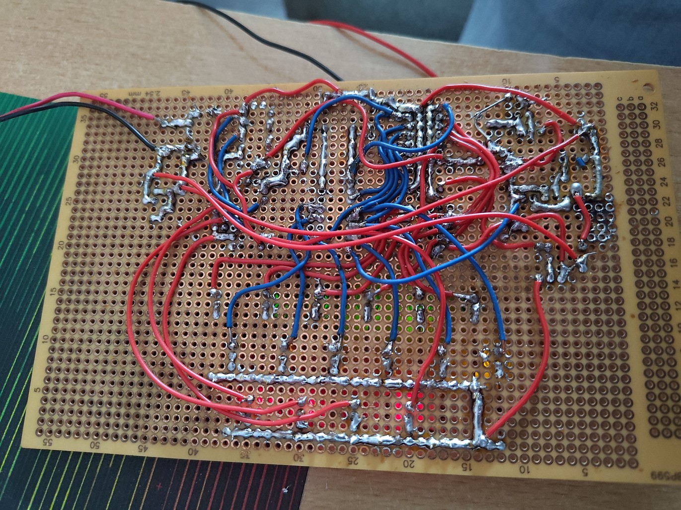
A good looking front, hid a hideous backside with a ton of wires i can barely recall how i did it. Think it was about individually going from chip to chip.
Discussions
Become a Hackaday.io Member
Create an account to leave a comment. Already have an account? Log In.