 FoxHood
CLOCK Generation
For Clock generation i'm using a common circuit with a 4060 Oscilator/14-stage ripple counter circuit. This chip can use a 32Khz Clock Crystal as a input and from this generate various frequencies on its output from 2048hz down to 2Hz.
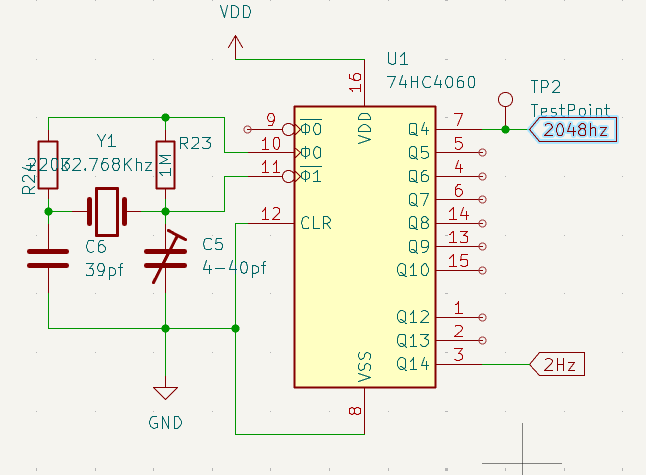
Its a simple, but effective. I employ a trimmer capacitor for on of the crystal leads and have the 2048Hz broken out to a pad. This should make it easier for me to calibrate the circuit for a more accurate clock signal with the help of my scope. Instead of just blindly hoping the accuracy isn't too bad as i did with the original.
Digit Logic
So idea is 6 digits being displayed in binary coded decimals.
The logic for the minute and second counters is straightforward. When a counter hits the values of 10 (8+2) for the first digit or 6 (4+2), the counter is to be reset and the next counter is to be clocked. This means that for each of these digits i only need a single 4-bit counter and a 2-input AND gate. The first digit will also need an OR gate if i want to clock in settings properly from switches.
One issue is that by using 4-bit counters i don't need more ICs than before (3x dual 4-bit, instead of 3x single 7bit), but also means i still gotta divide the frequency by 2hz anyway despite hoping not to have to do that. I'm going to use another dual-4bit. Its overkill, but it saves a special entry on the BOM.
At the hours it gets a little trickier as it ends at 24. Requiring the first digit to be reset at not just 10, but also at 4 when the second digit is 2. This requires the use of a OR gate for the first digit's reset and a AND gate to go off at the 24 hour mark.
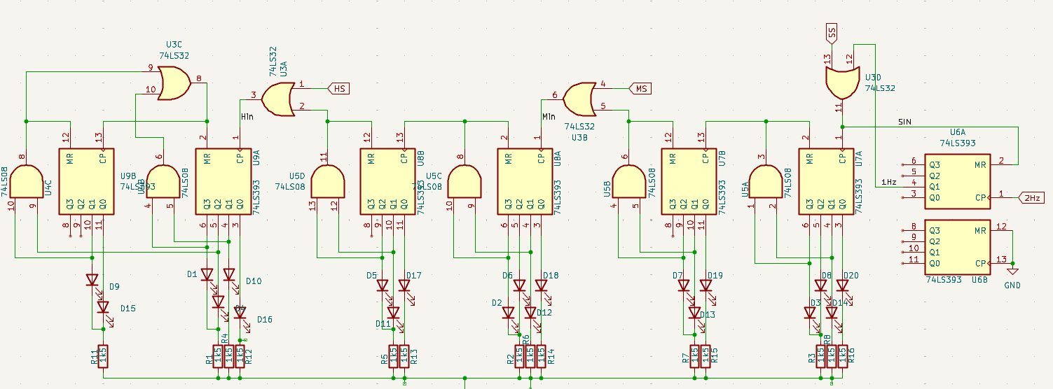
In total we need 7 counters , 4 OR gates and 6 AND gates. Rounded up in ICs that means: 4x dual 4-bit Counters, 2x quad 2-input AND and 1x quad 2-input OR
side-note: A neat little thing i noted is that with every digit the top two Most Significant Bits are mutually exclusive. So i can have them share a resistor.
Switches:
For a proper switch that doesn't bounce. One needs to filter the bouncing out and trigger with preferably some Hysteresis. A common way is to use RC filter that is quickly drained by a switch, connected to a inverted Schmitt trigger that provides the hysteresis and sends out a positive pulse on button press..
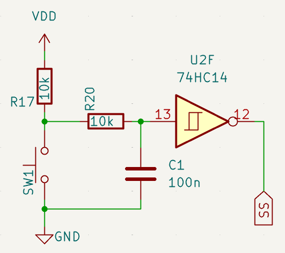
With three buttons for each of the pairs of digits. 3 Inverting Schmitt triggers are needed. standard logic ICs come with 6 of them so a single unit suffices.
IC Choice
If you looked at the schematics you will notice that the new ICs aren't CD4000 series. They are 74HC series.
These are the most popular incarnation of the logic series today. Boasting a very high speed, supply current in the micro-amps and very high input impedance. Pretty much all 4000 have pin-compatible counterparts within the 74HC series. Though it can take a moment to properly figure out the new number as while some ICs are just 75HC40** like the 4060. Many were renumbered.
In the end the ICs needed for logic are:
- 4x 74HC939 Dual 4-bit counters (4520 equivalent)
- 1x 74HC32 Quad 2-input OR (4071)
- 2x 74HC08 Quad 2-input AND (4081)
- 1x 74HC4060 14-stage binary counter (4060).
- 1x 74HC14 Hex Inverter Schmitt Triggers. (40106)
9 ICs in total. Not too bad, though it may become a pain during layout.
Discussions
Become a Hackaday.io Member
Create an account to leave a comment. Already have an account? Log In.