The parts used are as follows:
- attiny85-20pu microcontroller
- LM2596S buck converter
- sharp PC817 optocoupler
- 5V Relay Module
- 12 volt submersible pump
- Panel mount toggle switches
- Enclosure (x2) (62-115-35 and 52-82-35) (one for relay and circuit, other for PSU guts)
- DIP 8 Socket
- 12 volt 2.5 amp power supply (already on hand)
- 1/2" to 3/4" brass garden hose adapter ($7 at the hardware store)
- 4 small bolts and 4 small nuts ($4 at the hardware store)
- 10k ohm resistor (already on hand)
- perfboard and various wire (already on hand)
- teflon tape (already on hand)
- silicone (already on hand)
- spade connectors (already on hand)
The $25 dollars takes into account the price of everything, including what I already had and acts as a worst case scenario price. Some of these links are for lots of items. The $25 only accounts for the unit price of items used. At the time of building, I wasn't sure what all I'd need which is why I went to the hardware store for the hose adapter, nuts, and bolts. Considering how much I paid for them, I recommend you source them online.
If I were to do this again, I think I'd rather use a mains powered submersible pump. Doing so would eliminate the buck converter and large 12 volt adapter. Only a small 5 volt adapter would be needed. There are panel mount NEMA receptacles that would allow for easy install and removal of the pump. The relay would switch the mains to that receptacle instead of the output of the 12 volt adapter. Currently I'm using wire nuts to connect the switched DC 12 volts to the pump, however I plan on changing that to a molex connector or something similar.
In order to get the pump to fit in the bucket, I had to use a dremel to make routes for the pump power leads and discharge hose. There was already a hole for the gravity outlet, but instead of routing the discharge hose out of it, I decided to make another one as I didn't want the dripping water to snake up the outside of the hose onto the ground.
For the installation of the electronics, I gutted the 12 volt wall adapter, soldered power leads to the input, placed said guts into the larger enclosures, drilled holes for the bolts and wires, ran the wires through the hole, and bolted it to the chassis. Silicone was applied to seal the enclosure from moisture. The same steps applied for the main circuit, buck converter, and relay with the smaller enclosure. The wall adapter's input leads were spliced into the dehumidifier's power cord, the optocoupler's input was connected in parallel with the bucket full indicator LED, a switch was installed to interrupt the buck converter's output, and a hole was drilled to route the switched 12 volts to the pump.

 Engin
Engin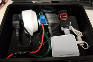
 mark.reeves.78
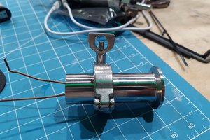
 Steve Hernandez
 Justin Scott