 x3e
x3e
In this project, I will describe how I built a tiny Arduboy clone using a cheap handheld console from the discount bin. A few pragmatic choices are highlighted that enabled me to finish this project in only one day. Hopefully, reading this will help you to build your own tiny terrible console or inspire you in other projects.
First encounter
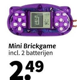
In a stroke of either good or bad luck, I encountered this handheld console that is both cheap and roomy enough to house some extra brains, but still small enough to compete in the Tiny Games Challenge :). Enter the Wibra "brick game", a relic from the discount bin with just the right mix of nostalgia and potential. After unpacking the console, I discovered that it was not really playable, due to the screen not displaying all lines correctly and with terrible contrast.
Building the Test Setup
The part bin provided a treasure trove of components that fit inside the console’s case. An SSD1306 OLED display is exactly the same width as the original screen, and an Arduino Pro Mini was planned to take residence where the original piezo speaker once lived. (I was especially happy to find a good use for that Arduino, because I almost always use ESP* socs now.) I planned on powering the thing with the original LR44 button batteries—because there would be zero space for a lipo. Besides, wiring and testing a lipo would have cost too much time for a one-day project.
I needed to build a breadboard setup to prove two things:
1: That both the Arduino Pro Mini and the screen were able to run off the two LR44 batteries.
2: The screen was actually an SSD1306 (the screen breakout board was not labelled and it had lived in my parts bin for at least 10 years).
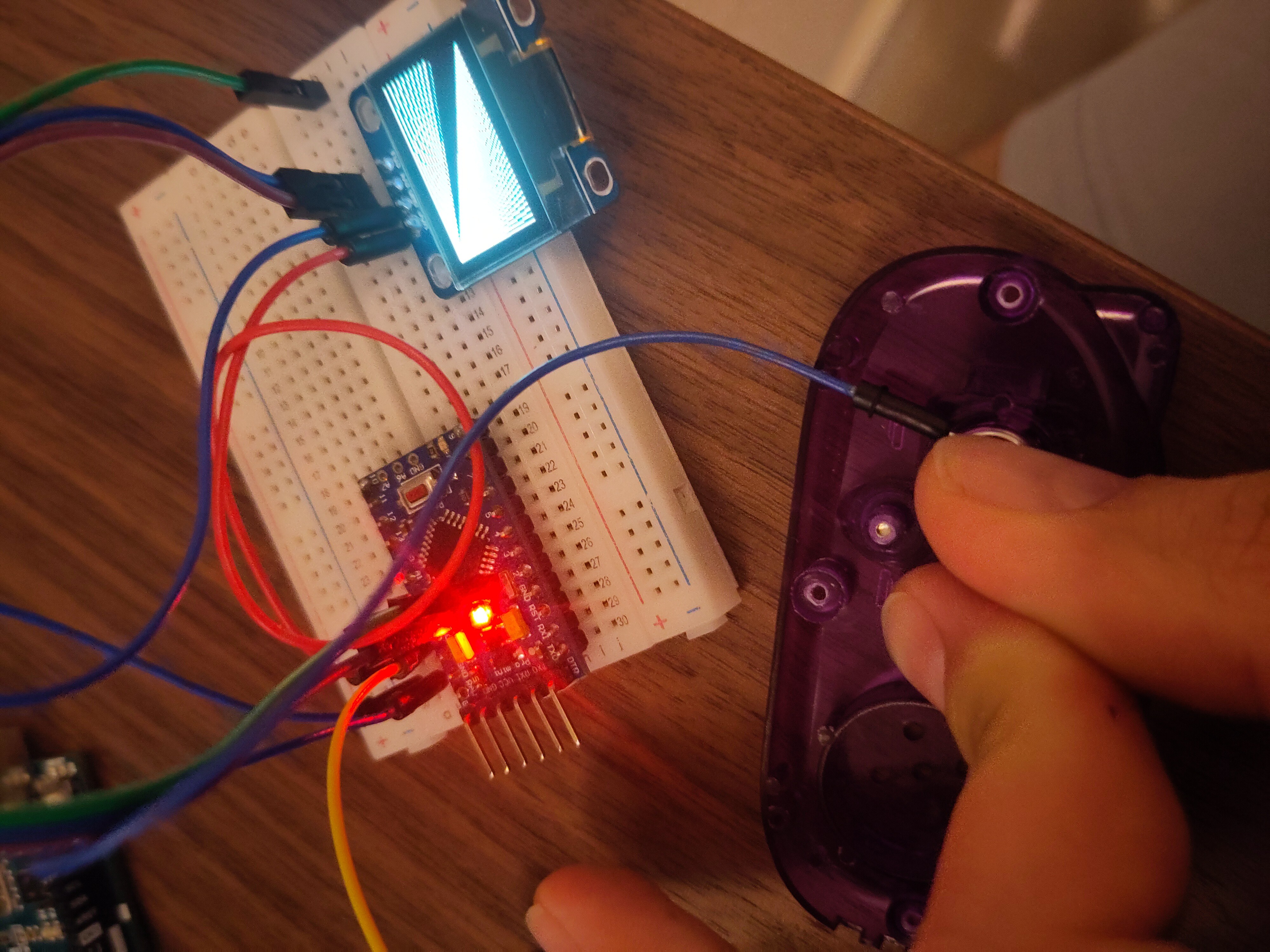
After wiring everything up on a breadboard and flashing some Adafruit example code, I crossed my fingers, powered it on, and voilà—the screen lit up. That's all I needed to test. Time to move on to the literal "hacking".
Fitting Components in the Case
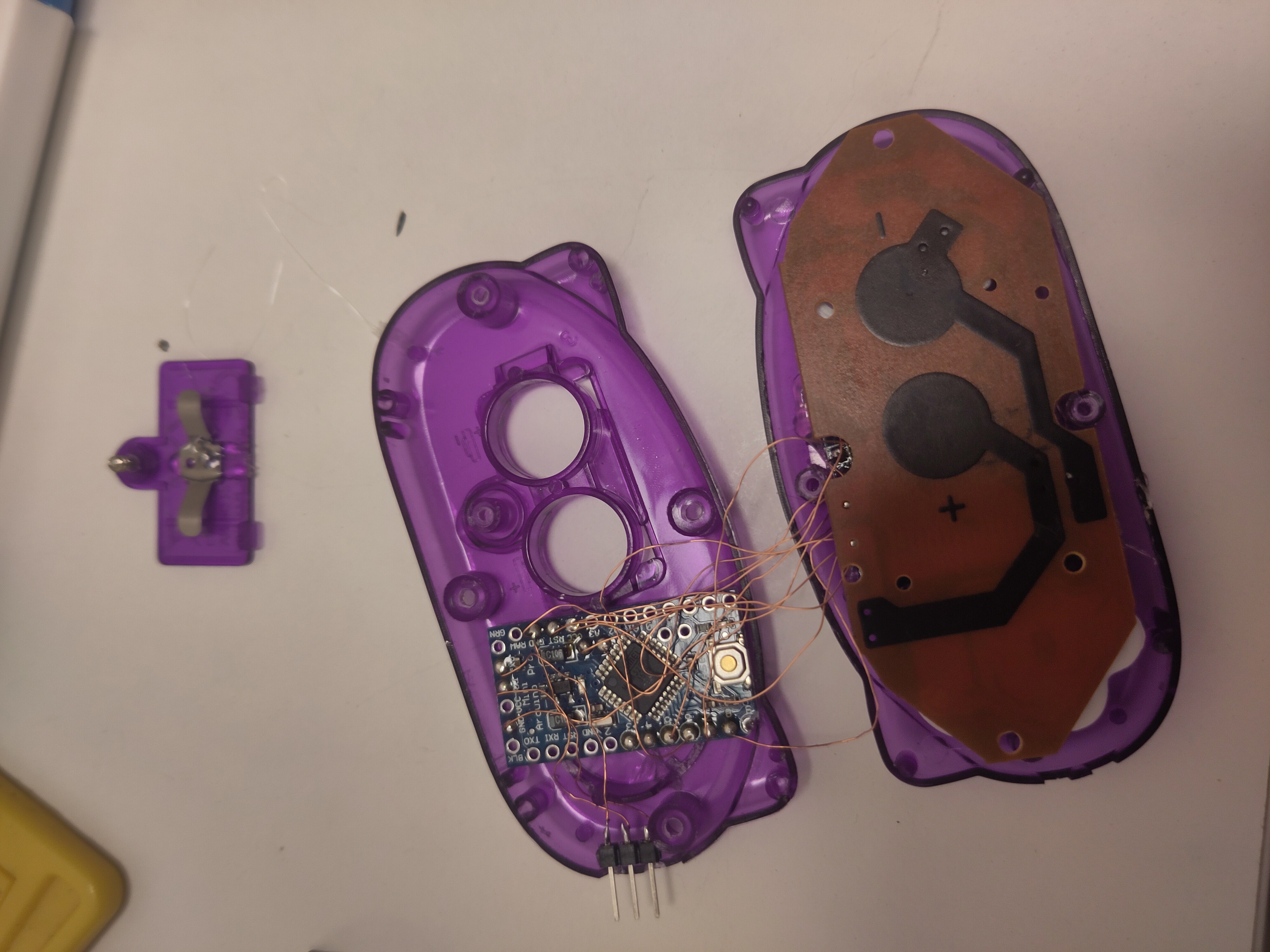
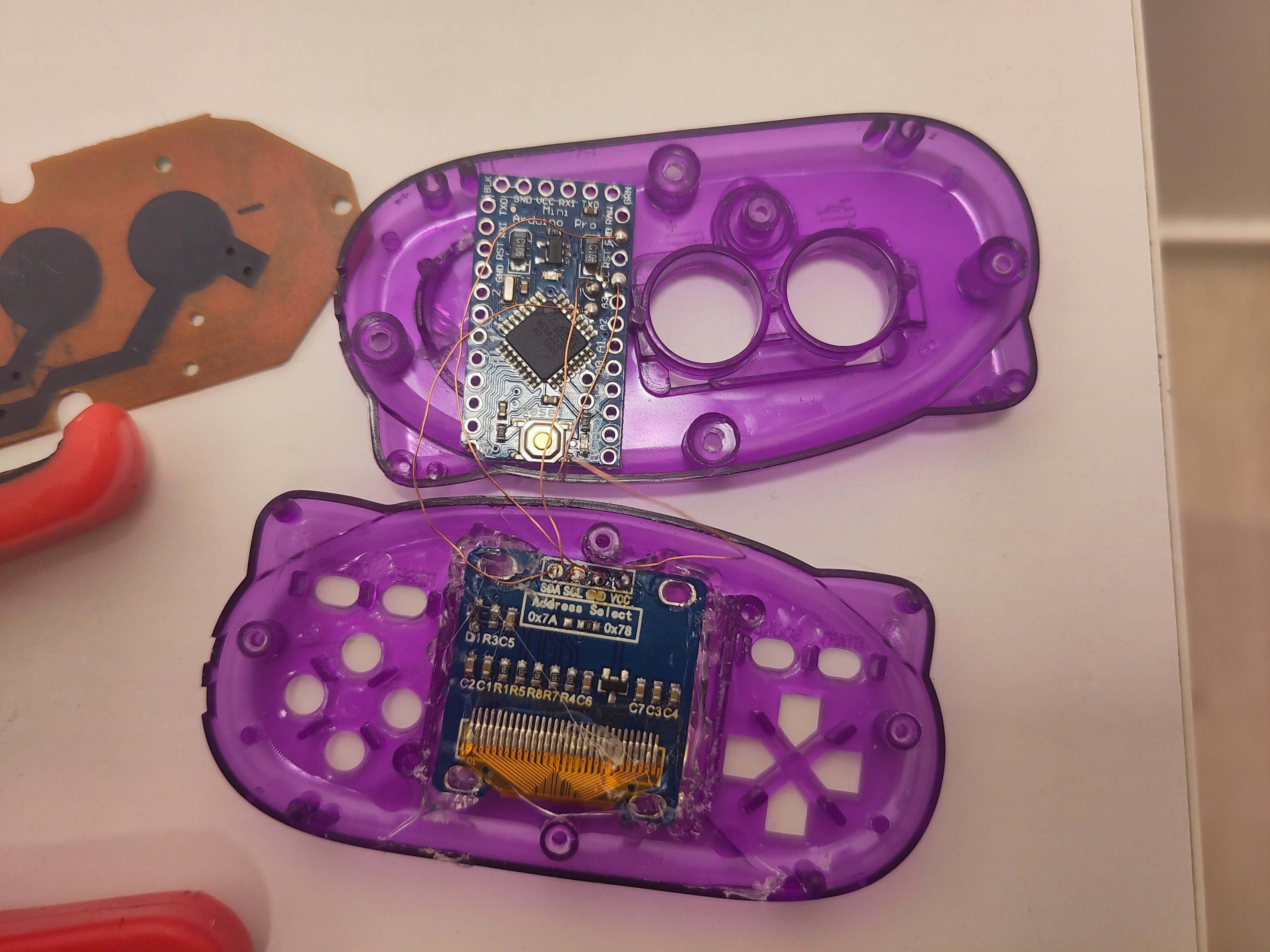
Next came the delicate operation of cramming everything into the case. With some pliers and a lot of determination, I hacked away at the extra plastic. Hot glue became my best friend, holding everything in place. Magnet wire connected the components, and I decided to leave the original PCB intact so that the original rubber dome switches could be used. I didn’t overthink it—I simply started wiring all traces that led from the buttons to the original blob CPU directly to Arduino digital pins. Time was ticking, and this was a one-day build. I figured I’d sort out the button mapping in software later (and that bit me in the back later). The final touch was cutting the power traces to the original blob CPU—no hard feelings, buddy.
Making the Buttons Work
While wiring up the buttons I was quite puzzled. The first few buttons looked simple: just directly wired between GND and an CPU pin. Then I discovered four buttons wired in parallel to the same pin. I guess Wibra’s chief electronic designer thought having four "action" buttons would boost sales. Even though they can only serve one function.
Then, as I encountered buttons wired between two CPU pins, it dawned on me: the buttons were multiplexed. Luckily, they did it in a smart way: the left and right buttons never need to work simultaneously, and neither did up and down. The fire button, reset button and on/off button all have their own dedicated pin.
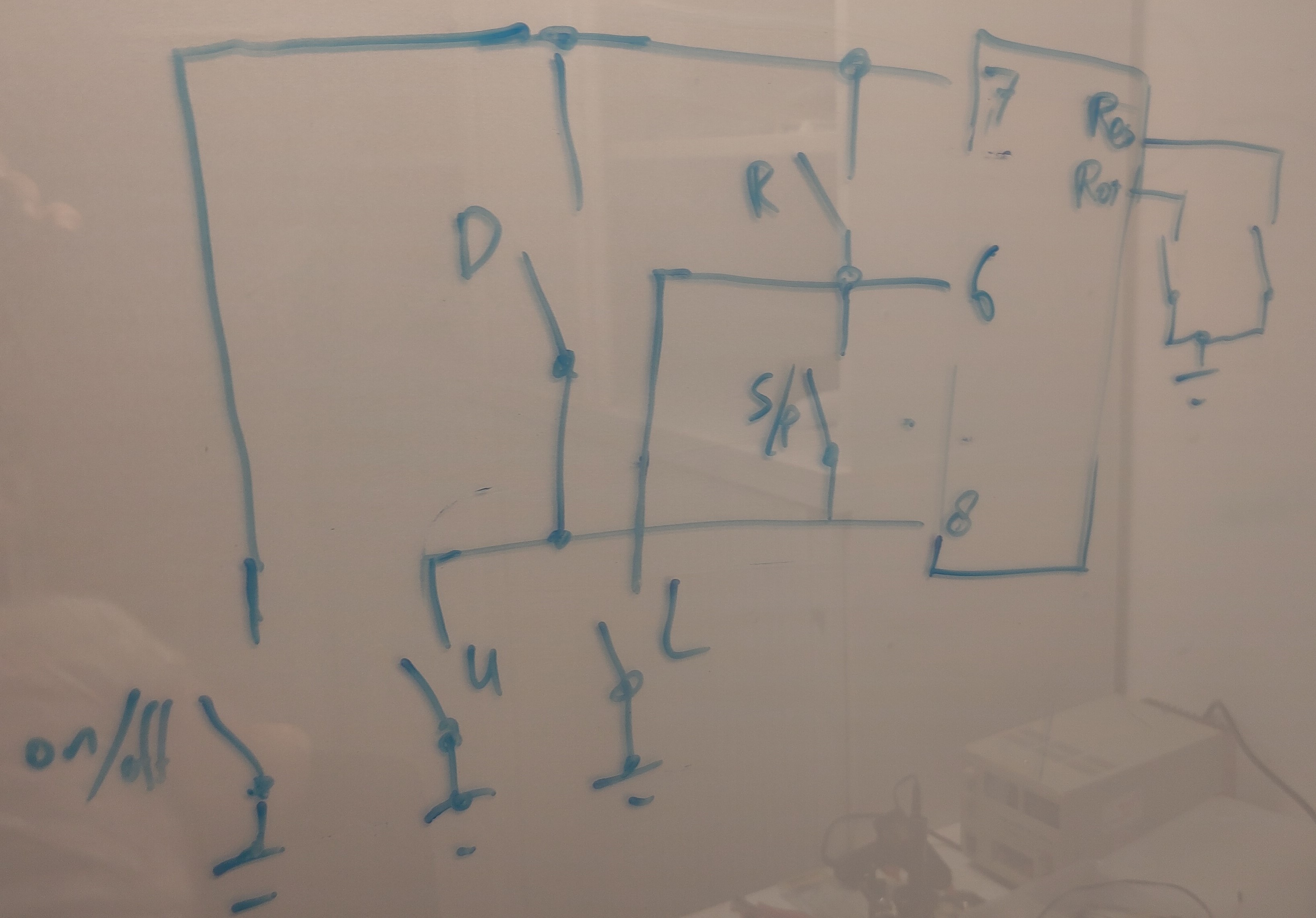
After working out the schematic (thank goodness for those pre-solder PCB photos!). I got the Arduino to read the buttons correctly:
// Check buttons directly connected to a ground pin
 if (!digitalRead(UP_BUTTON_PIN)) { buttons |= UP_BUTTON; }
 if (!digitalRead(RIGHT_BUTTON_PIN)) { buttons |= RIGHT_BUTTON; }
 if (!digitalRead(A_BUTTON_PIN)) { buttons |= A_BUTTON; }
 if (!digitalRead(B_BUTTON_PIN)) { buttons |= B_BUTTON; }

  if (!(buttons & RIGHT_BUTTON) || !(buttons & UP_BUTTON)) {
    // Pull pin 7 low and check left and down buttons
 pinMode(B_BUTTON_PIN,...
Read more »

 JohnsonFarms.us
 Owl Labs
 gokux
gokux
 Michael Wessel
hah cute one