 Bruno Campidelli
To use fewer ESP32 pins, I need to multiplex the inputs as I have been doing already (using a matrix scan) but I can go further and add shift registers to save more pins!
However, the subject can be quite confusing and intimidating, at least to me. I thought I could use a single 74HC595 to scan both the COLUMNS and ROWS of my matrix, but it turns out I can't. That is because the 74HC595 is a serial IN and parallel OUT shift register. To scan a matrix I need to write to the columns (or rows, pick one) and read the rows (or columns if you have picked the rows before).
I bought a very nice module that has three 74HC595 chained, allowing you to expand your ports to a whopping 24 outputs! But I still need a way to read several inputs, and for that, there is another shift register called 74HC165.

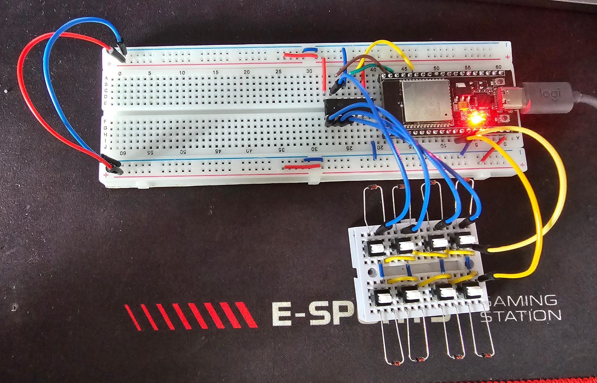
Since I am still waiting for my 74HC165 to arrive from China, I decided to use a small 74HC595 I had here to test the matrix scanning, using it to output signal to 4 columns and read the 2 rows using the ESP32 input pins.
Well, it didn't work. So I had to check if my shift register was working and for that, I had to learn more about it. So I checked this tutorial here (https://dronebotworkshop.com/shift-registers/) and it is amazing. Here is the Hello World example:
#include <Arduino.h>

// ST_CP pin 22
const int latchPin = 22;
// SH_CP pin 21
const int clockPin = 21;
// DS pin 23
const int dataPin = 23;

void setup () {
  // Setup pins as Outputs
  pinMode(latchPin, OUTPUT);
  pinMode(clockPin, OUTPUT);
  pinMode(dataPin, OUTPUT);
}

void loop() {
  // Count from 0 to 255 and display in binary
  for (int numberToDisplay = 0; numberToDisplay < 256; numberToDisplay++) {
    // ST_CP LOW to keep LEDs from changing while reading serial data
    digitalWrite(latchPin, LOW);
    // Shift out the bits
    shiftOut(dataPin, clockPin, MSBFIRST, numberToDisplay);
    // ST_CP HIGH change LEDs
    digitalWrite(latchPin, HIGH);
    delay(500);
  }
}
And the demo!
Now that I now that my shift register IS working, I had to recheck the wiring and my program, it turns out that I had misread the data pin GPIO number and set it to 27 instead of 23. Now it is working! And it supports multi-pressed buttons! Here is the sketch:
#include <Arduino.h>

// Pin definitions
const int DATA_PIN  = 23; // Data (SER) -> GPIO 23
const int CLOCK_PIN = 21; // Clock (SRCLK) -> GPIO 21
const int LATCH_PIN = 22; // Latch (RCLK) -> GPIO 22

// Matrix dimensions
const int COLS = 4;
const int ROWS = 2;

// Row pins
const int rowPins[ROWS] = {12, 14}; // Row 1 -> GPIO 12, Row 2 -> GPIO 14

// Column to 74HC595 mapping
const int colPins[COLS] = {0, 1, 2, 3}; // Q0 to Q3 on the 74HC595

// Array to keep track of button states (0 = not pressed, 1 = pressed)
bool buttonStates[ROWS][COLS] = {false};

// Set a specific column LOW by controlling the 74HC595
void setColumn(int col) {
  uint8_t colValue = ~(1 << col); // Set only the selected column LOW
  shiftOut(DATA_PIN, CLOCK_PIN, MSBFIRST, colValue);

  // Latch to transfer the data to output pins
  digitalWrite(LATCH_PIN, LOW);
  digitalWrite(LATCH_PIN, HIGH);

  // Small delay to allow the shift register output to stabilize
  delayMicroseconds(10);
}

void onButtonPress(int button) {
  Serial.print("Button ");
  Serial.print(button);
  Serial.println(" pressed");
}

void onButtonRelease(int button) {
  Serial.print("Button ");
  Serial.print(button);
  Serial.println(" released");
}

void setup() {
  // Initialize the Serial
  Serial.begin(115200);

  // Set up the row pins as inputs with pull-up resistors
  for (int i = 0; i < ROWS; i++) {
    pinMode(rowPins[i], INPUT_PULLUP);
  }

  // Set up the control pins for the 74HC595
  pinMode(DATA_PIN, OUTPUT);
  pinMode(CLOCK_PIN, OUTPUT);
  pinMode(LATCH_PIN, OUTPUT);
}

void loop() {
  for (int col = 0; col < COLS; col++) {
    // Set the current column to LOW
    setColumn(col);

    // Check each row for a key press
    for (int row = 0; row < ROWS; row++) {
      int currentState = digitalRead(rowPins[row]);

      // Determine the button number (1 to 8 in this case)
      int button = row * COLS + col + 1;

      if (currentState == LOW && !buttonStates[row][col]) {
        // Button was just pressed
        buttonStates[row][col] = true;
        onButtonPress(button);
      } else if (currentState == HIGH && buttonStates[row][col]) {
        // Button was just released
        buttonStates[row][col] = false;
        onButtonRelease(button);
      }
    }
  }

  delay(50); // Debounce delay
}
The next step is to make sounds with this setup!
Discussions
Become a Hackaday.io Member
Create an account to leave a comment. Already have an account? Log In.