Guido
GuidoOVERVIEW
I was in doubt to publish it, because many similar project have been published in the past years.
However, I supposed that my experience could be useful to anybody.
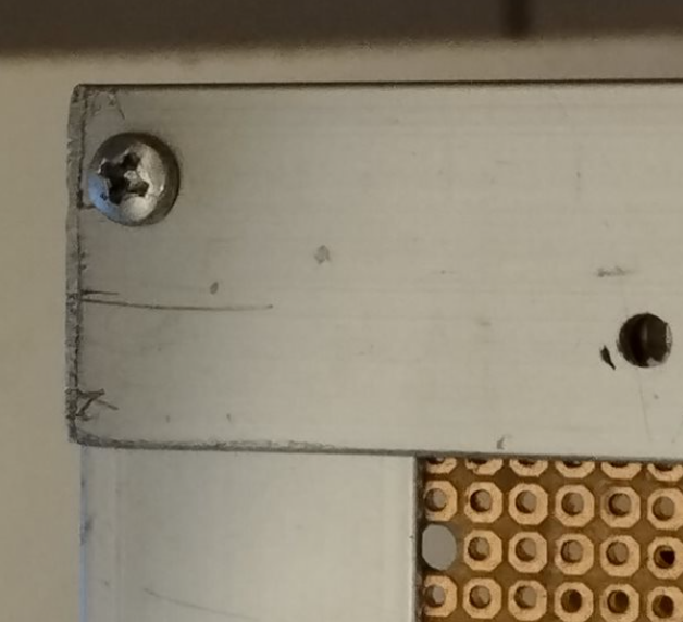
CHASSIS
It is made using extruded aluminium:
L shaped for the base
square shaped for the balancing legs
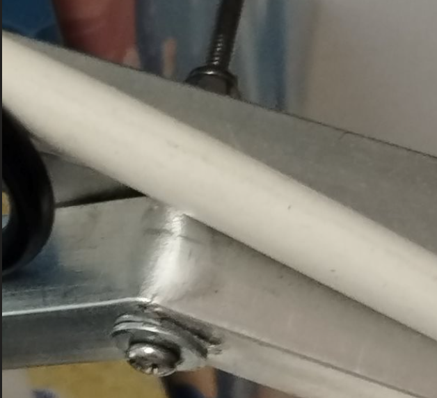
U shaped to cover the Servo motors and square shaped to enclose the wheel motors
Every piece is connected using M2 or M2.5 nuts and bolts.
So you need only a drill, iron file, iron saw, clamps and screwdrivers to build it. An angle grinder could be useful to proceed more rapidly.
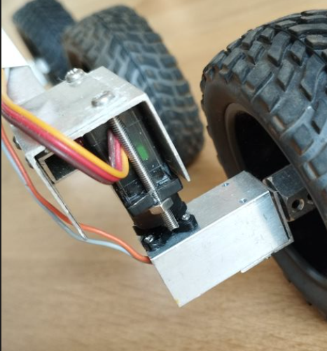
WHEEL MOTORS
After a few attempts, I chose the DollaTek DC 3V 35RPM 3mm Shaft Mini Metal Gearwheel Gear Motor GA12-N20
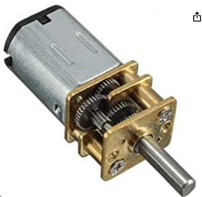
As you can see it has also two useful M2 screw holes in the front plate.
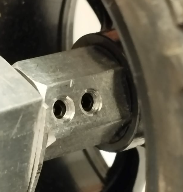
WHEELS
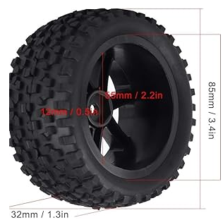
Each wheel is connected to the motor shaft with an hexagonal joint.
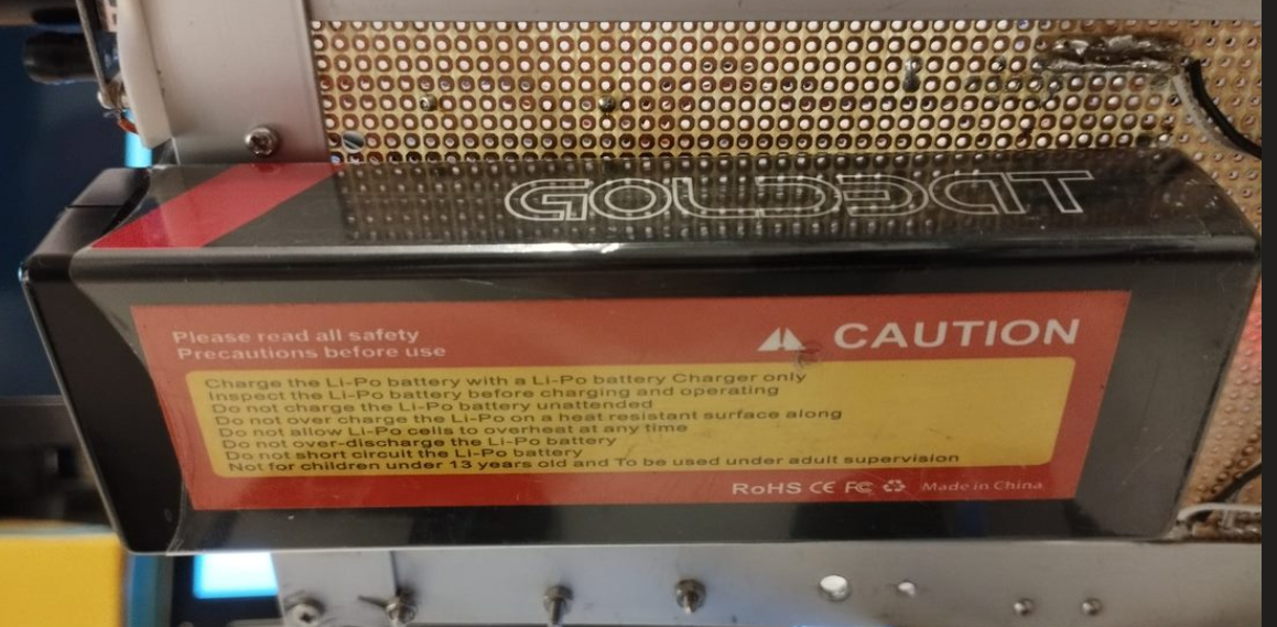
BATTERY
I chose a 7.4V 5000 mAh LIPO battery that I glued with bi-adhesive tape to the bottom of the chassis.
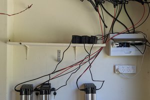
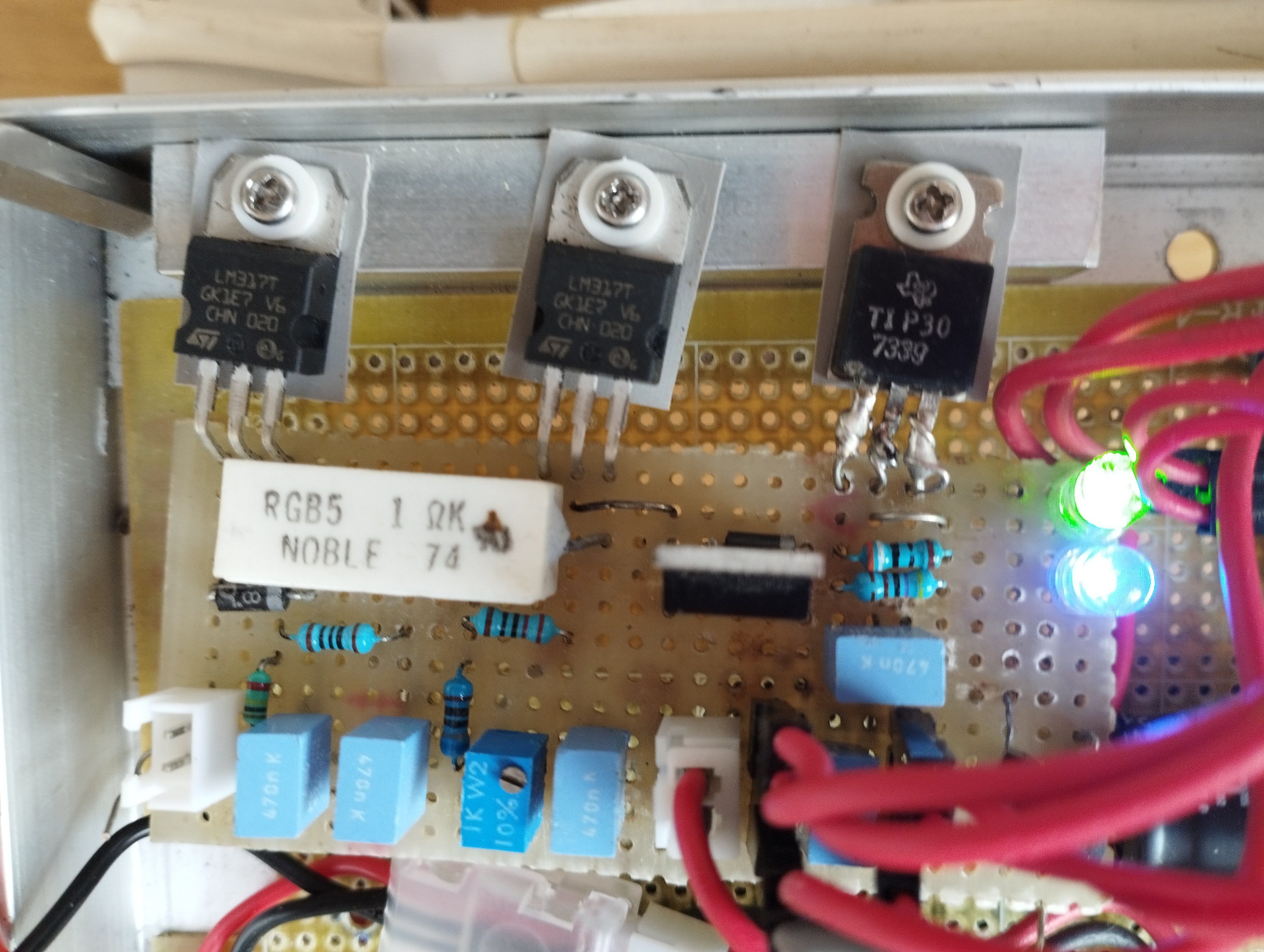
SCHEMATICS
Battery Charger and Power Supply
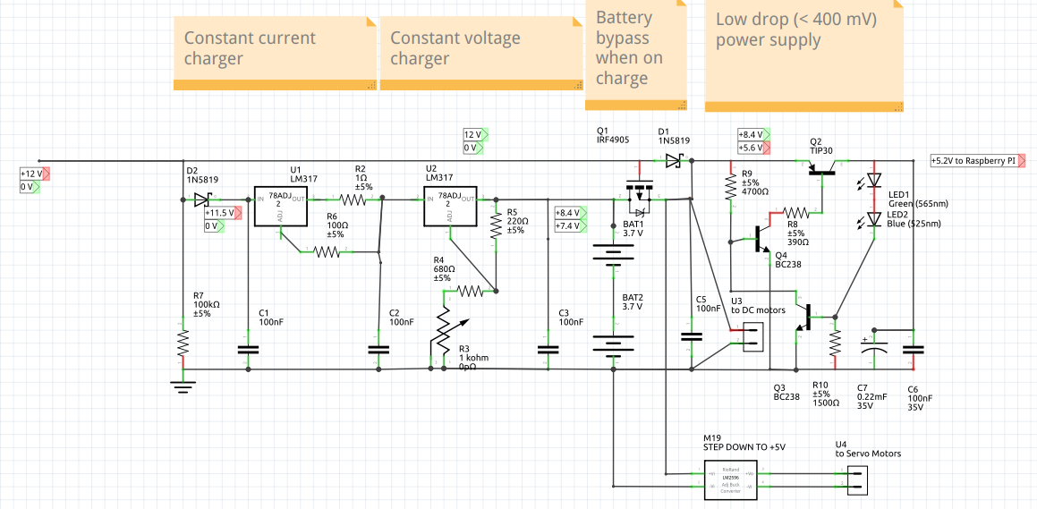
A few notes:
- It must be supplied with 12V 2A
- the constant current for the the first phase of charging is 1.2 A
- the constant voltage charger is regulated to 8.4 V (before connecting the battery) by R3
- Q1 and D1 let to bypass the battery when the battery charger is supplied. In this way the LIPO battery is charged at its maximum.
- The low drop power supply is able to the Raspberry PI Zero W with 5.2 Volts even if the LIPO battery is as low as 4.8 Volts.
- The two LEDs (green and blue) let to obtain the 5.2 Volts reference voltage.
SOFTWARE
The source code and all its documentation is in the linked Github repository https://github.com/guido57/RPI-Rover.
 Roger
Roger
 Lucas Rangit MAGASWERAN
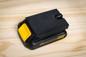
 Vitor de Miranda Henrique