 moosepr
With the day job and general life getting in the way of play time, there is only a limited window to work on the project and to update you guys on how things are going. Anyone following along in other places (mailing list/discord/socials) might be a bit more up to date, so lets bring you all up to speed.
if your in a rush, the TL:DR is that im still working on it, and v0.3 of the pcb has just been ordered!!
So last time on the CL-32 show, we were talking about case options, but I was mulling over the retro pocket computers and their printed sheet metal faces, and wondered how I could reproduce that. Im sure that with a little bit of hunting, I could find someone to create those for me, but that seems like a complicated way round it!!
There was a lightbulb moment when i realized that I have access to some precision manufacturing that would allow nice crisp edges and even some artistic elements too!! Enter the humble PCB!!!
I did a test design and got it ordered in 0.8mm PCB. The idea was to create a recess for the PCB to sit into, so we get the best of both worlds!! A nice printed case, and then a slick looking face to top it all off
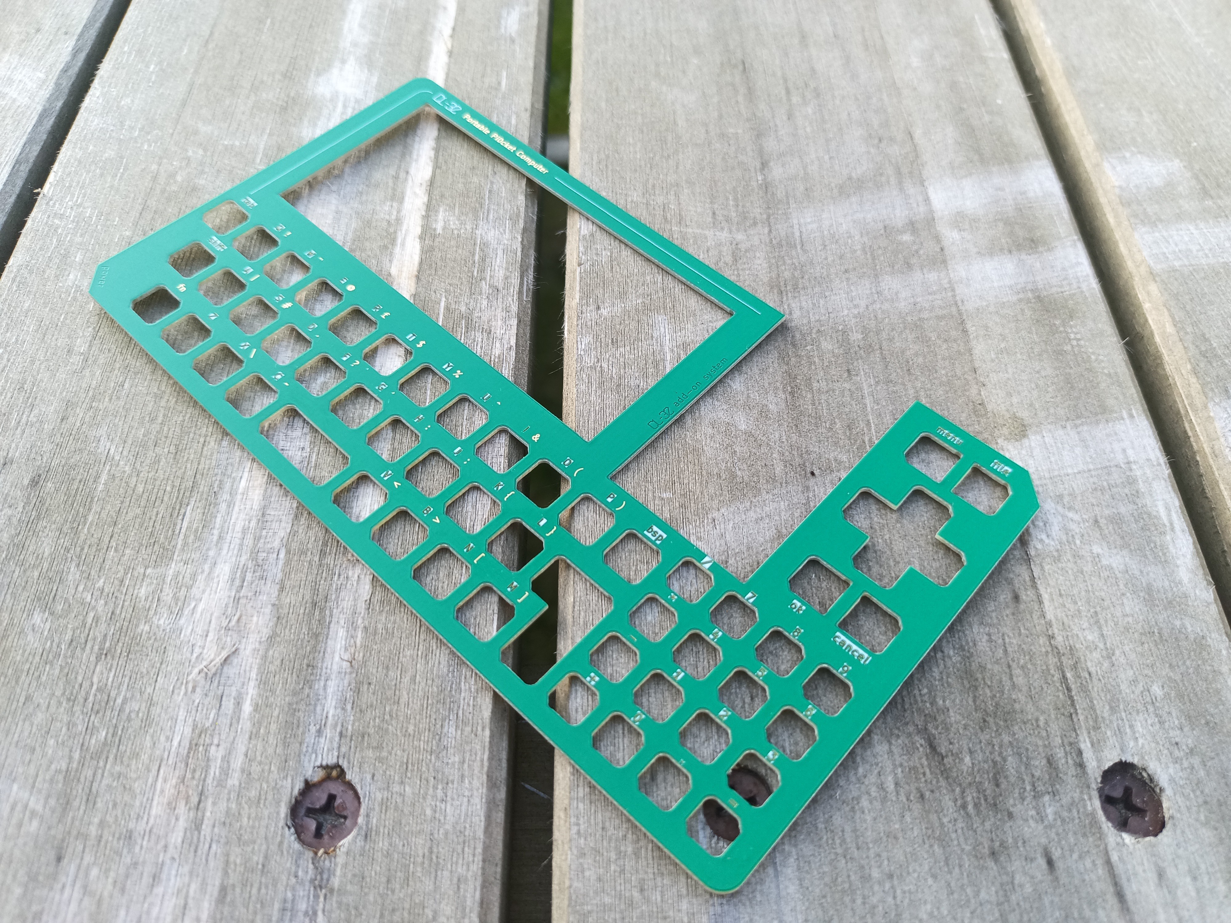
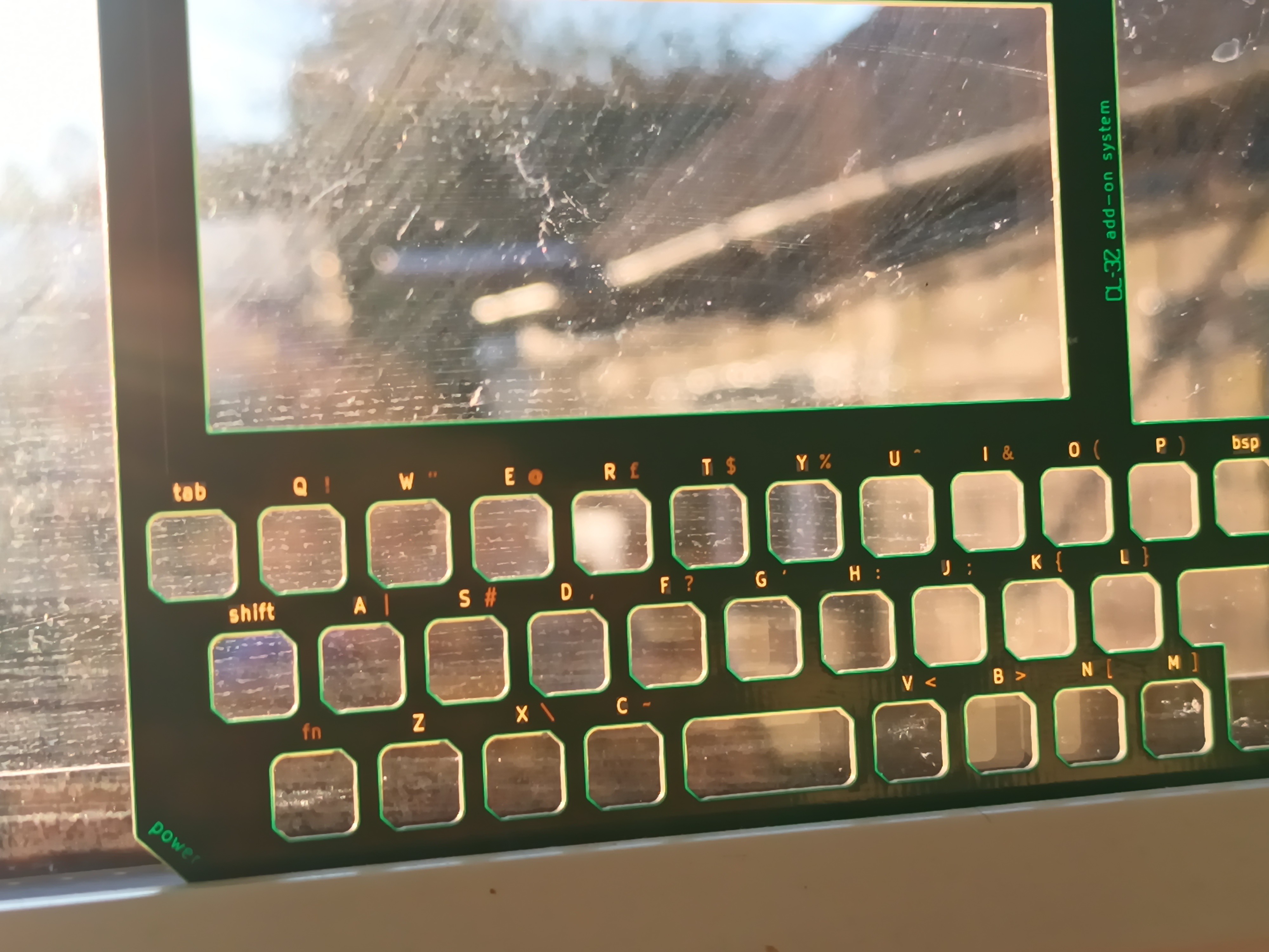
The test was mostly a success, The legends were cut into the copper layer as well as the solder mask, so that they could be illuminated by a backlight if the mood struck me!! There was supposed to be a nice silkscreen border round the legends, but that wasnt great. Also it never looks as big in real life as it does on the screen!!
I think i might have also neglected to tell you that the buttons were getting a bit of a jiggle too!!
The point at which all this fell down was actually trying to get the front of the case to house the PCB. With the plastic cut away for the PCB, it became so thin and flimsy that it was almost impossible to print, and then removing the support material just left broken bits!!
So the thinking cap came on again. I had a nice PCB face, a main PCB for the guts of the device, and I could whip up a simple PCB plate for the back too, but how to secure it all??
I have seen some projects solder lots of PCB plates together to form a case, but i wanted softer corners and the ability to disassemble for battery changes and even repair. There is also the option of using threaded posts and screws, but that would still leave the corners of the PCB exposed
After a bit of thinking there was another lightbullb moment, why not make a snug band that grips all 3 boards at the same time...
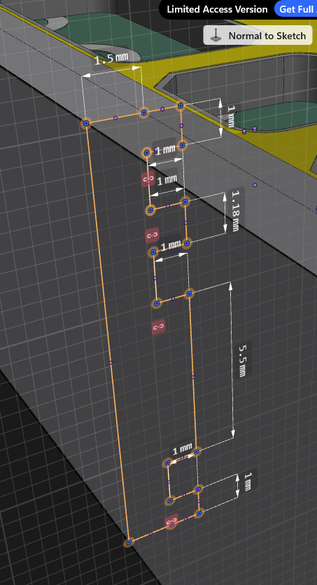
that same profile all the way round could make it quite sturdy, assuming the material was firm enough, but would still allow you to pop it apart if needed. So I printed up some simulated PCB blanks so that i could drop them into a TPU print to save wasting lots of material on supports. The PLA blanks have a lower melting point than the TPU, so they stuck together pretty well. It came apart in the end
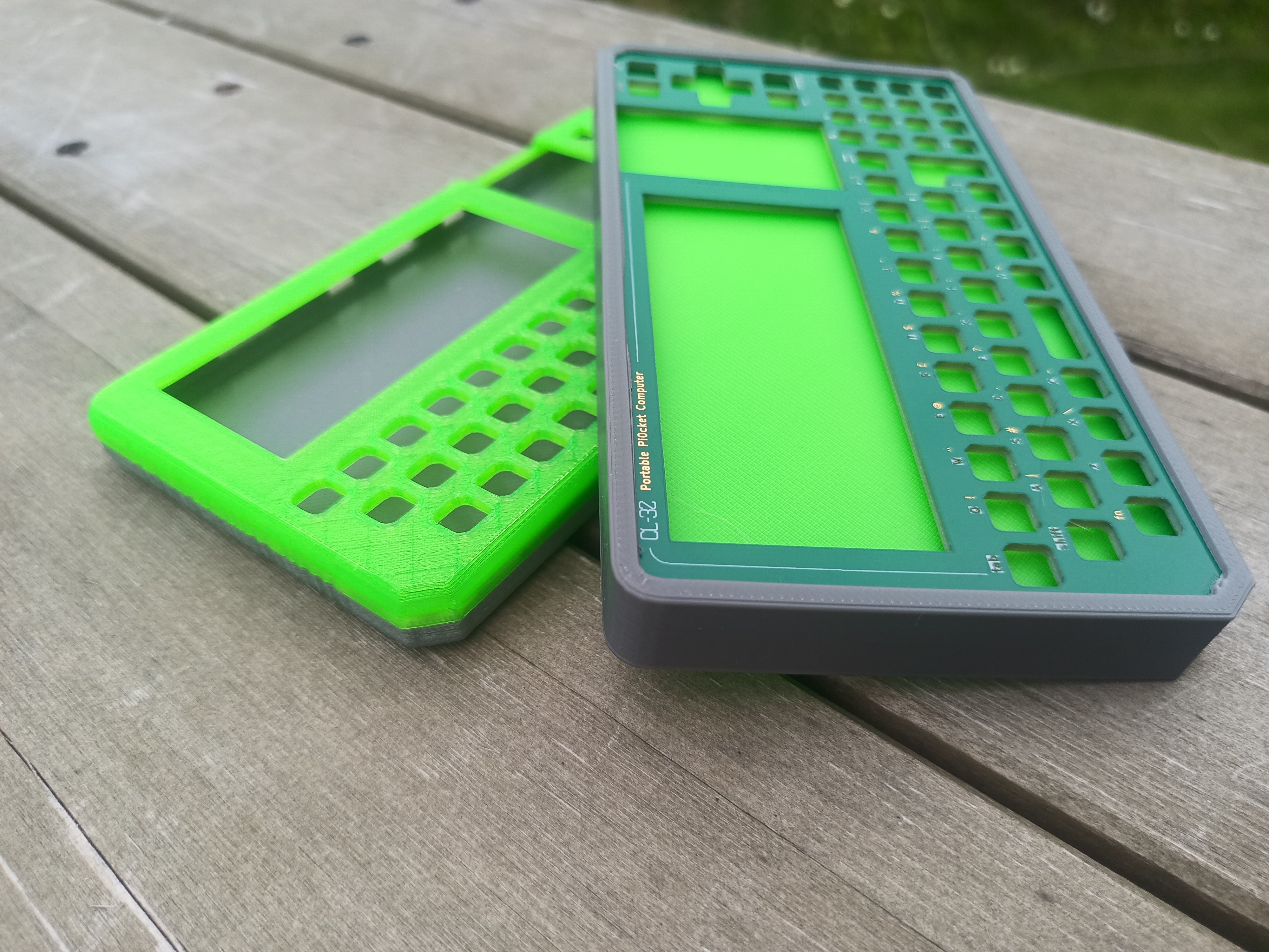
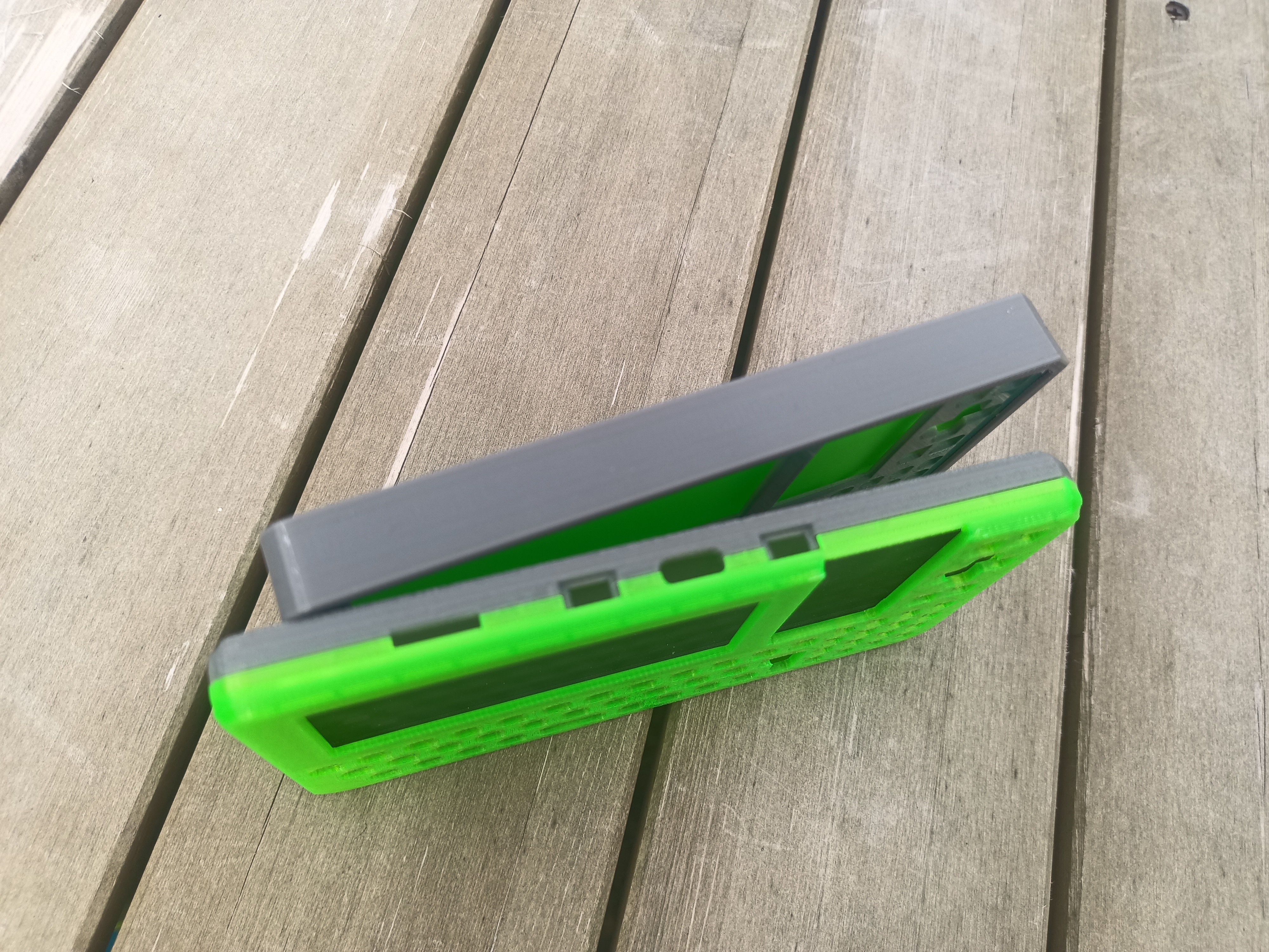
It makes it look a bit more chunky, but its only 2mm thicker. There is more scope for softening the edges and makeing it look a little more rounded, but it proves the concept and I can play with that while im waiting for PCB fab
so back to KiCad we go, and the faceplate gets a good dose of the awesome KiBuzzard label tool to make the legends pop
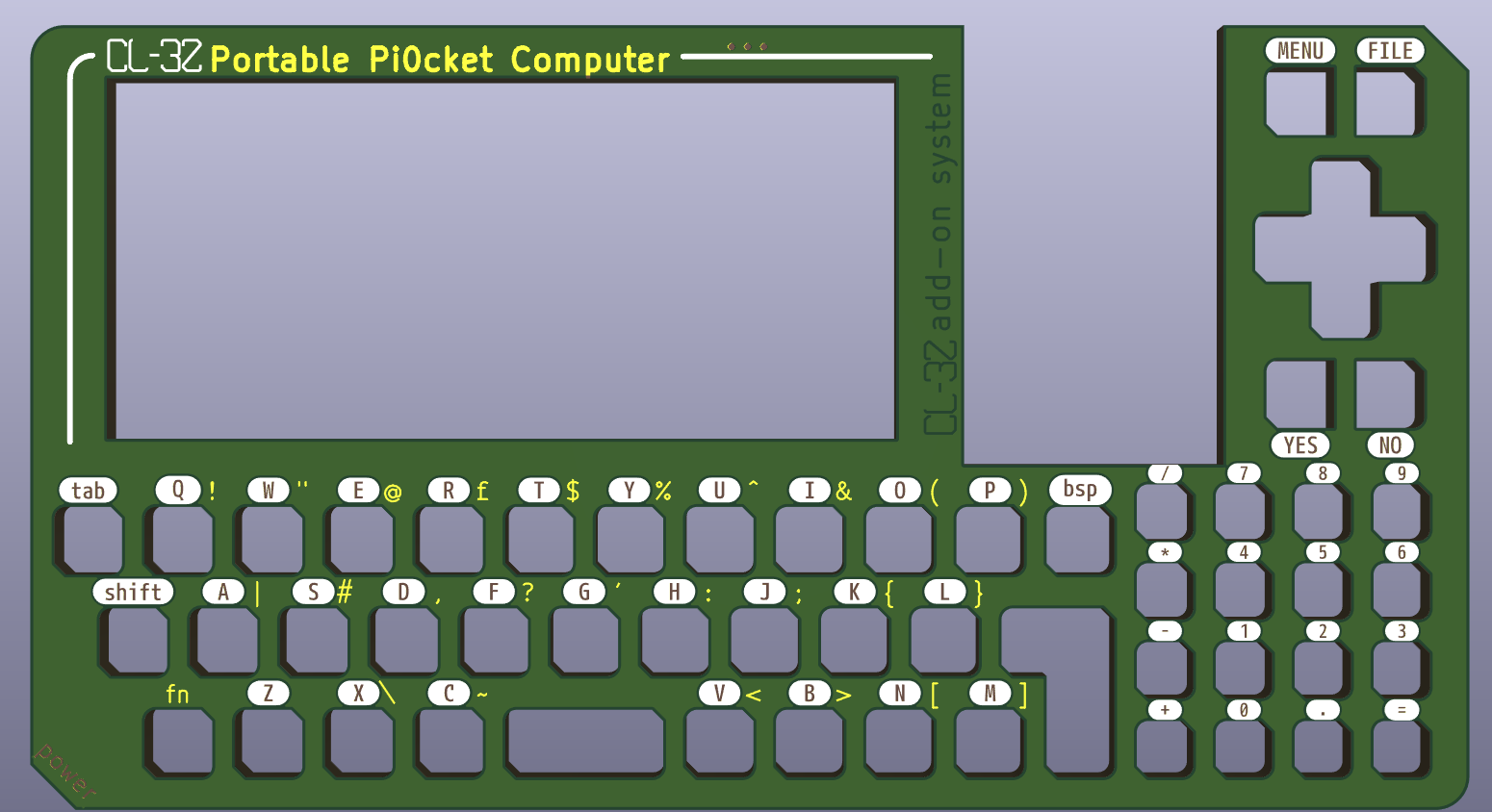
The main PCB gains an i2c battery fuel gauge to get round some silly analog read issues i was having, and that free's up a pin for some 'neopixel' backlight led's for the keyboard. These are a little power hungry, so I have made them switchable. There have been a few other tweaks, the keyboard has had a shuffle, the m.2 socket has moved to allow some navigation buttons to be available up at the top right for easy access
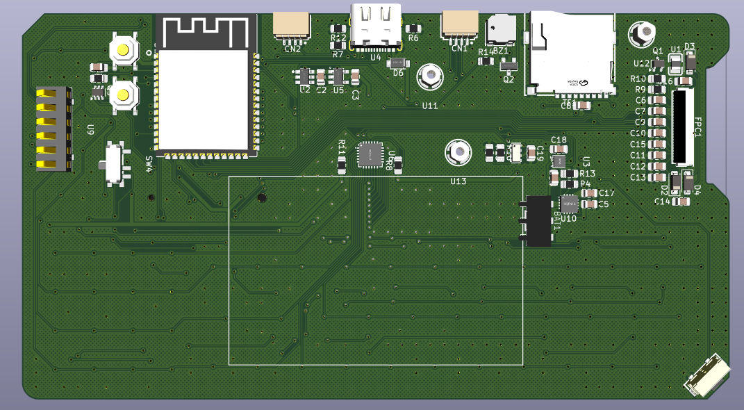
I even added some threaded posts which would allow the mounting of external hardware if an add-on card were to need an external antenna or something ;)
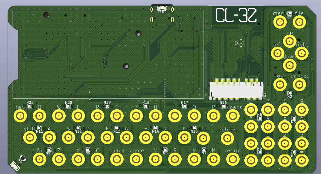
Speaking of which, i had the idea of trying to make the back PCB a bit more useful and bake in some small PCB antenna's.
I know they wont be great, but should allow some basic functionality, and no doubt the spring connectors between the boards will mess things up big time, but you never know until you try!!
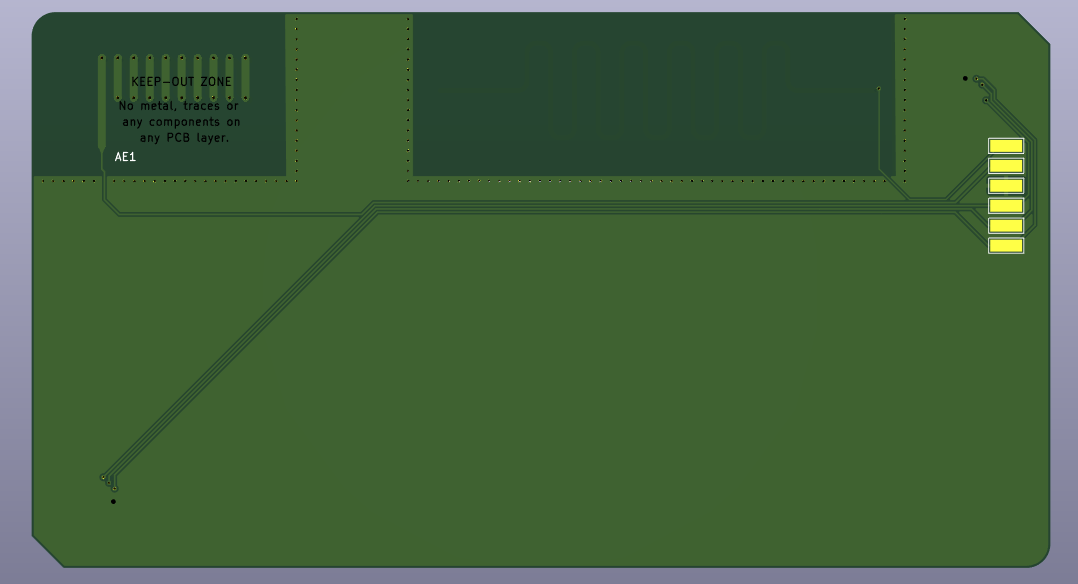
The antenna on the left should be LoRa frequency, and the one on the right should be good for 433mhz for some general wireless shenanigans.
So the boards have been ordered, a full set of 5, all fully assembled and ripe for playing with. I will get better at posting on here to keep you all updated for if your not following on elsewhere...
to be continued...
Discussions
Become a Hackaday.io Member
Create an account to leave a comment. Already have an account? Log In.