 moosepr
I had been working away on v0.3 of my project. It wasnt a massive change, fixed some issues with the past board, and added a few new tweaks to make the whole project better. After many hours starting at the schematic and pcb design, i finallly plucked up the courage to order the boards for assembly. I could save some pennies and just buy boards from one place and components from another, but the time I have to spend tinkering is limited, and they would end up sat waiting for me to get round to it.
My PCBA company of choice is Makerfabs. I have worked with them in the past on my TinyPi project, and their work is always fantastic. They have helped me find parts that are not normally accessible through the conventional channels, and even spotted issues with my BoM!! I can highly recommend them :)
The boards really are beautiful!! (and I really should get the good camera out!!)
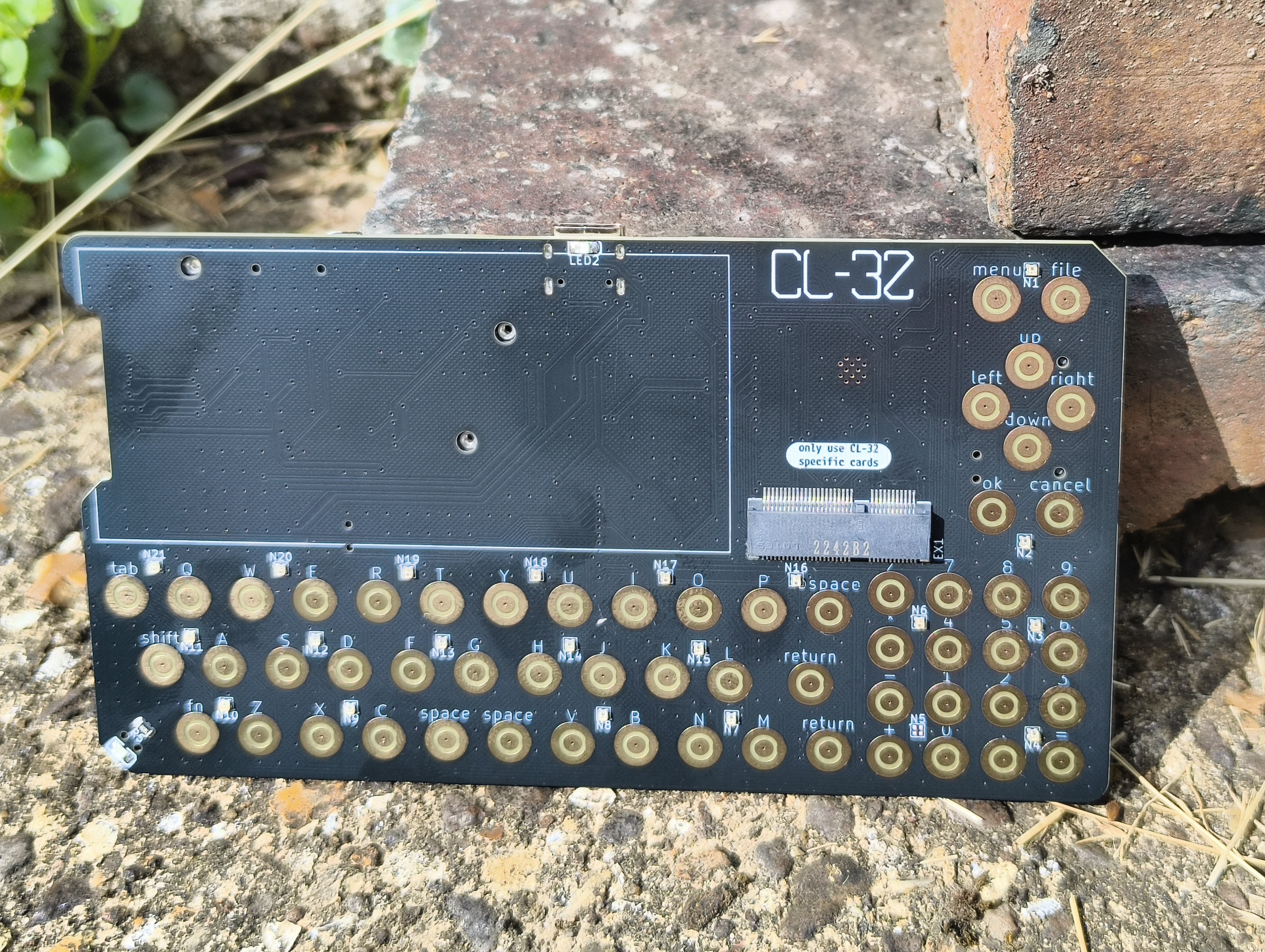
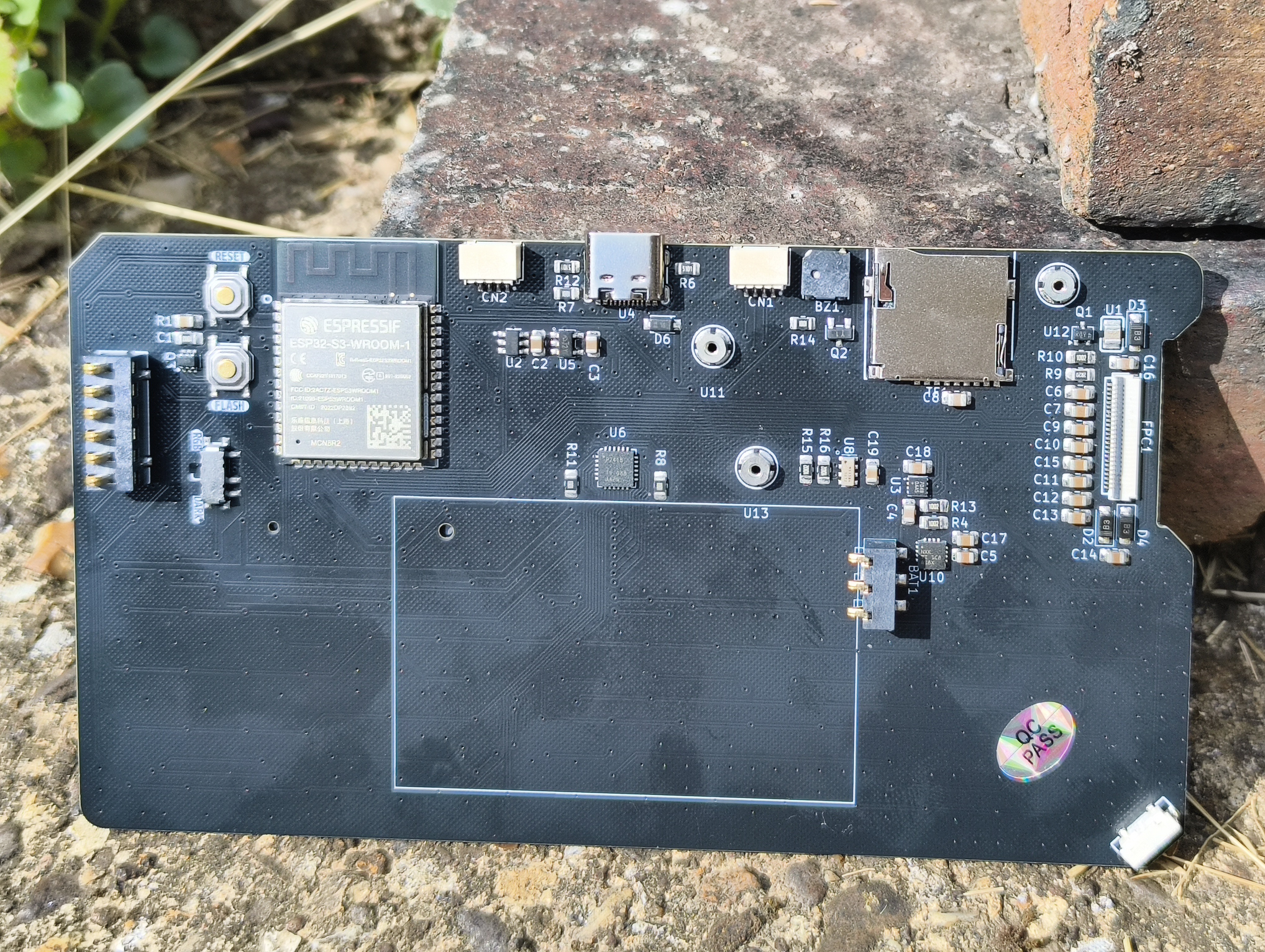
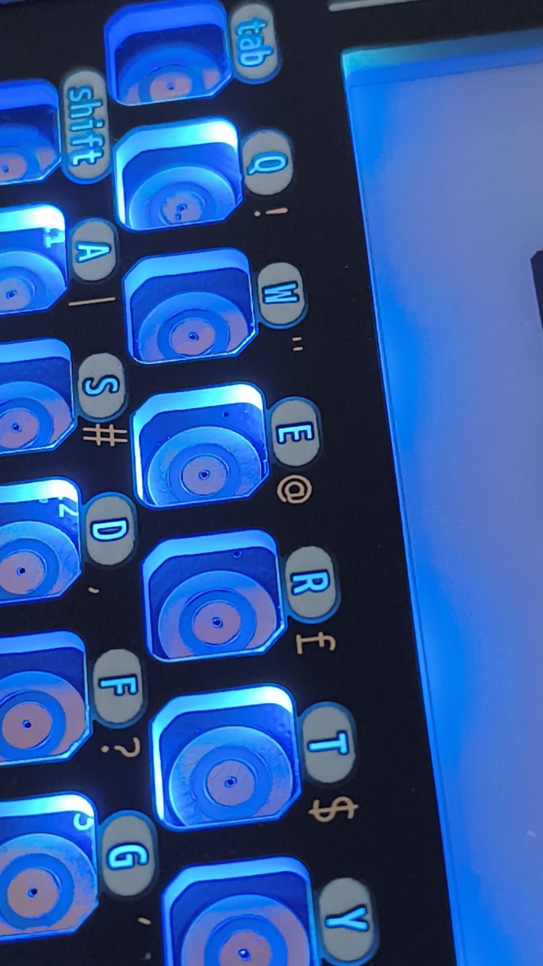
The biggest change the eagle eyeed amongst you will see is the re-shuffle of the keyboard. In testing the last version, it became apparent that the navigation buttons would be much better suites on their own, which resulted in a moving of the add-on slot. There is a new addition of a li-po fuel gauge IC to make battery monitoring much simpler, and to free up an extra pin to allow for another of the big changes. The keyboard now has a string of WS2812 LED's within it, to allow for some RGB fun if that floats your boat!! The flash/reset buttons have been tucked away on the back of the board (I have never needed them, but i wouldn't be confident removing them completely), and there is a slide switch to cut the power to those fancy LED's if they suck more power than you like. There is also a spring connector on the back to allow connectivity to a back plate PCB. This passes power and gnd, and also passes i2c, and 2 additional connections for antenna usage. That would allow an add-on card to connect to an antenna built in to the back of the device, rather than having a dedicated external antenna. This would never be as good, but should be great for testing.
The front PCB idea has had a little bit of polish too!! The silkscreen cutouts have been given the kibuzzard treatment, and the legends have been made as large as possible to maximize visibility
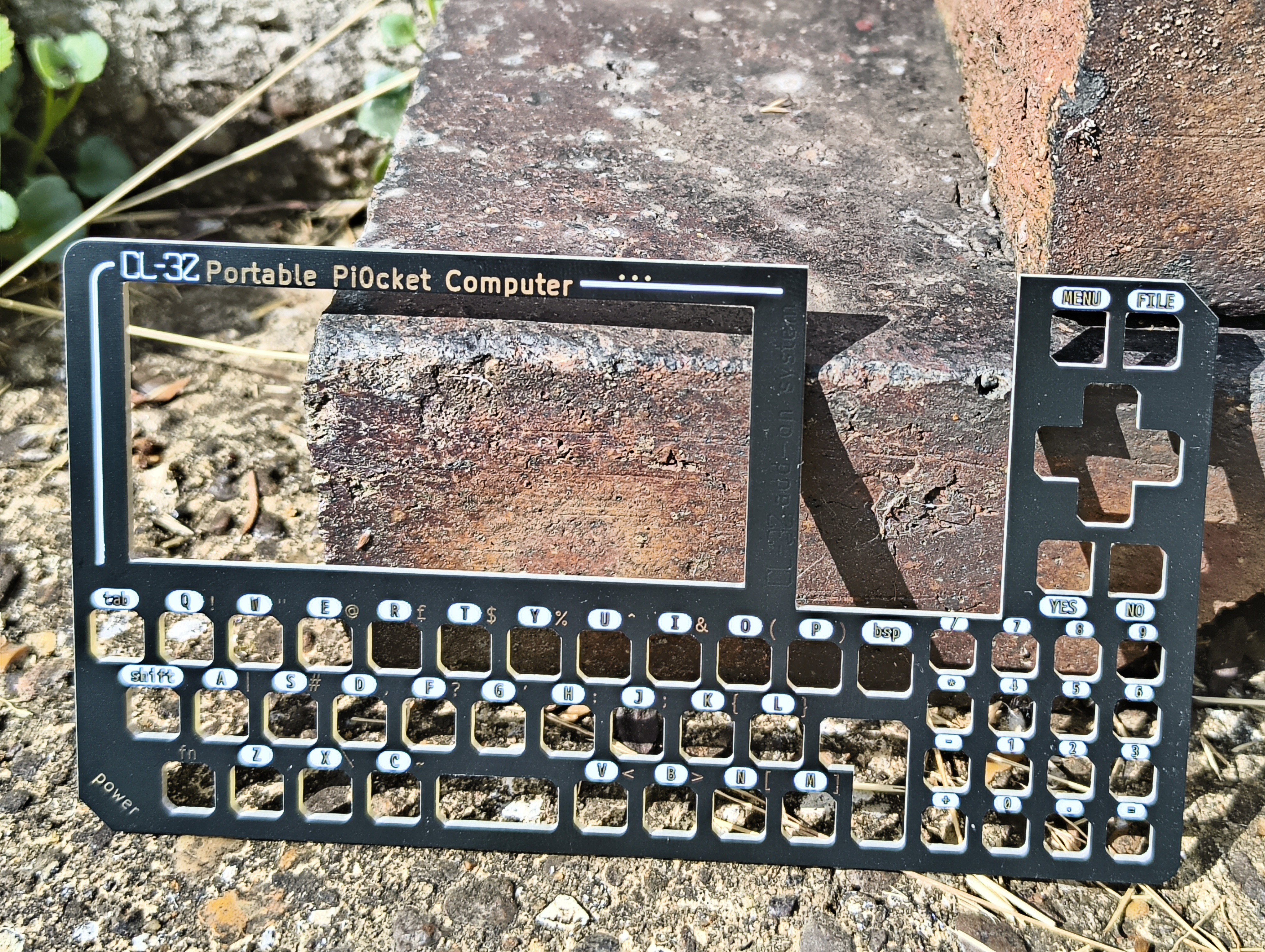
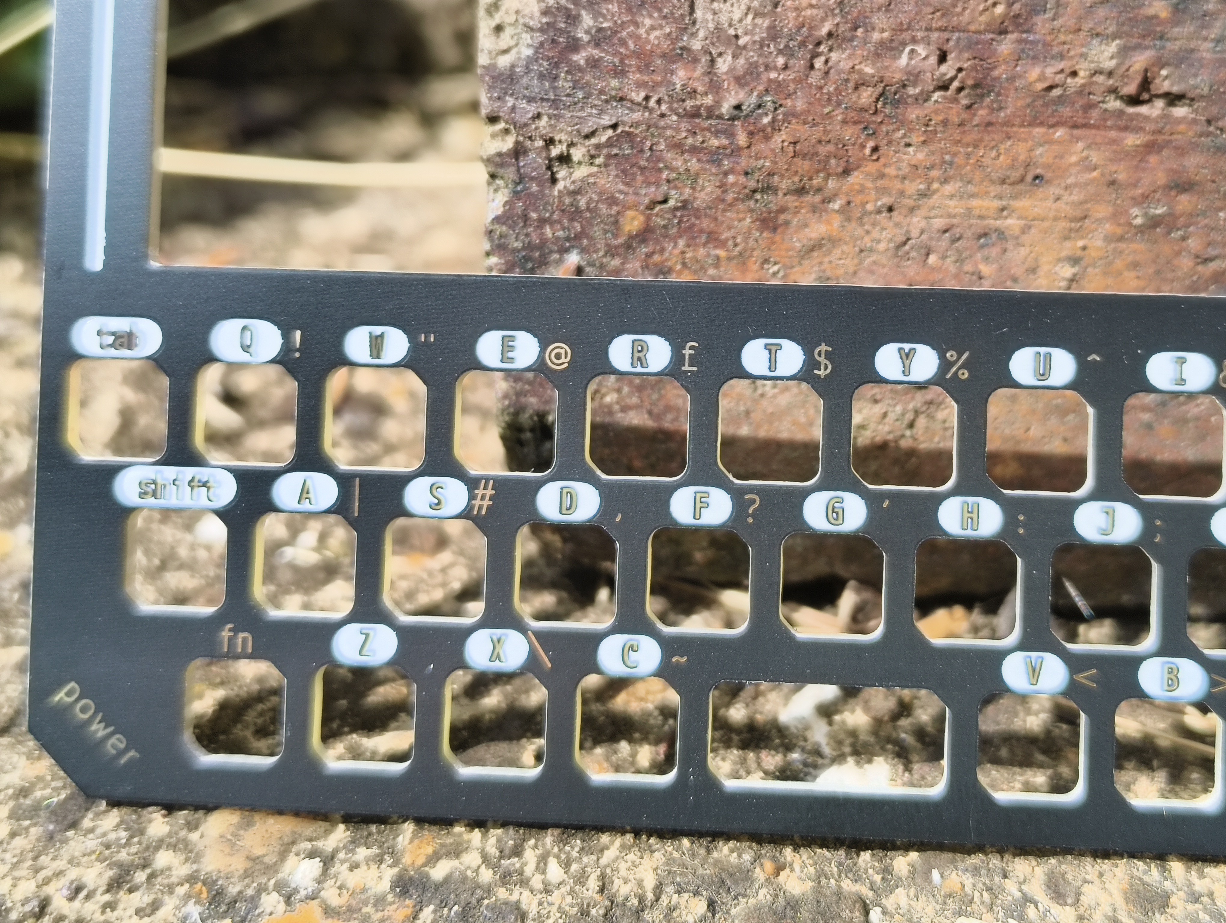
The back of the PCB has been stripped of all copper and solder mask so it is bare fiberglass. This would allow the LEDs packed into the keyboard to shine into the fiberglass and shine though the legends on the face. This gives a mighty fine effect if I do say so myself!!!
Stay tuned for more updates :)
Discussions
Become a Hackaday.io Member
Create an account to leave a comment. Already have an account? Log In.
Something I've discovered using LED's for use in darkness is they don't need to be that bright. And the difference between 100% brightness and %30 power wise is huge. Also a brighter LED In full darkness is irritating to my eyes so I prefer as dim as possible. I know pwm is one way to control brightness, otherwise higher value resistor. Or possibly have each LED have a lower value resistor then have a variable resistor that feeds all of them...
Either way nice to see your progress I don't get on here much and haven't had the ability to work on my own projects but nice to check up.
Are you sure? yes | no
yeah they can be a bit bright!! you will be able to set the colour and brightness in settings, and even turn them off all together if thats what you want. I tried to make sure the legends work for both backlit and not, so hopefully it covers all bases
Are you sure? yes | no
I have to say that the method you used for the backlight sure does look slick!
Are you sure? yes | no
yeah it looks great!! there is a bit of light leak round the actual buttons, but it still looks nice. little bit power hungry, but im working on ways round that, and will add the ability to turn it off too
Are you sure? yes | no