Choosing the microcontoller
When I was planing the entire project I also decided to make it more
challenging and interesting to me. And because of that chose a bit
unusual MCU for this watches. My pick stick to ATtiny85 - I beleived
that it would be an interesting challenge to make watch on this MC, but
later I had to switch to ATtiny85 and I will describe why so. Most basic
MC for such project would be ATmega328, which is used in Arduino UNO,
but again, it was not interesting enough to me and the solution on this
MC is already exist on the net.
Another reason why I’ve chosen AVR MCU but not ARM (STM32) or other is
because I’ve already had enough knowledge and skills about programming
such MCUs.
So, as you probably know, ATtiny85 has not a lot of pins, actually there
are only 5 pins which I could use to run an entire watch! It means that
I had to design various drivers and multiplexers to drive all the
devices with which ATtiny communicates.
Display driver
The key devices which are driven by MCU are of course indicators
HDSP-2000, without them entire project has no any sense. Due to the lack
of available pins in MCU, display driver should receive data from a
small amount of pins. If we look closer at the indicator, we’ll see that
it is basically a shift register which receives data through SPI bus. It
can be inferred, that the most vital signals for indicator are serial
clock and serial data signals. All other signals can be generated from
clock and data signals and I will explain how.
First of all, let’s have a look at columns signals. Each time a high
voltage level is applied to one of these pins the corresponding columns
in LED matrix are driven and the LEDs in this column emit light. It
means that after the new values have been stored to the shift registers
the next column should be driven. Basically, it is very similar to the
“running leds” projects, which can be easily built on decimal counters
like CD4017. Each time a new data is stored to the shift registers of
indicators, the counter CD4017 will count to the next value and the
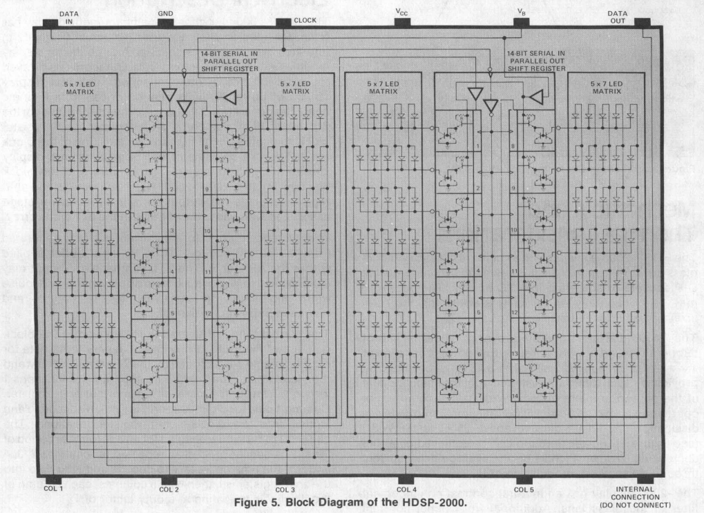
corresponding output pin will drive the column of indicator. Schematic
of indicator is shown on fig. 1.

Figure 1. - HDSP-2000 indicator schematic
Another problem is to get know when the transition of data to shift
registers is finished. This issue also can be solved with counters. By
counting the number of bits, which were transferred, it can be checked
whether or not the process is finished. In HDSP-2000 there are four
shift registers and each of them stores 7 bits, so the total data
capacity of indicator is 28 bits. Since two indicators are used in this
project, the capacity of display block is twice bigger, which is 56
bits. The amount of bits which were sent to the display can be obtained
from serial clock signal – each positive front of clock represents a one
bit of data that has been stored to the indicator. To count bits a
binary 7-stage counter CD4024 was used. The binary representation of
decimal number 56 is 111000, so the corresponding pins Q3, Q4, and Q5
are high when counter reach value 56. Early mentioned pins are tied to
single AND gate with 3 inputs. Output signal of AND gate is used as
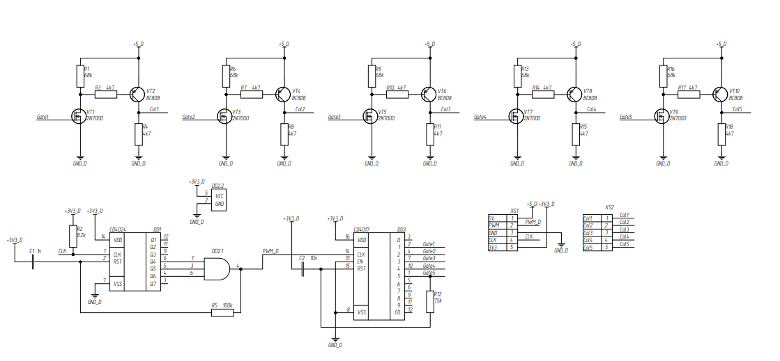
clock signal for decimal counter CD4017. Drivers schematic is shown on
fig. 2.

Figure 2. - Display driver schematic
Since indicator HDSP-2000 has
only 5 columns counter CD4017 counts only from value 1 to 5. When
counter reaches value 5, corresponding pin “5” changes its state from
low to high and through RC low-pass filter sets high level on signal RST
while simultaneously driving fifth column of indicator. When high level
is set on RST pin of counter it resets its value. RC low-pass filter is
needed to create a time delay, so the fifth column could be driven for
some consistent time. The same solution was used to the output of AND
gate in order make sure that positive clock front for decimal counter
CD4017 would not disappear instantly after binary counter CD4024 resets.
The signal from AND gate is also used...
 Vitalii


Thanks for the open source, how do I choose the value of component L1 in supply_core?