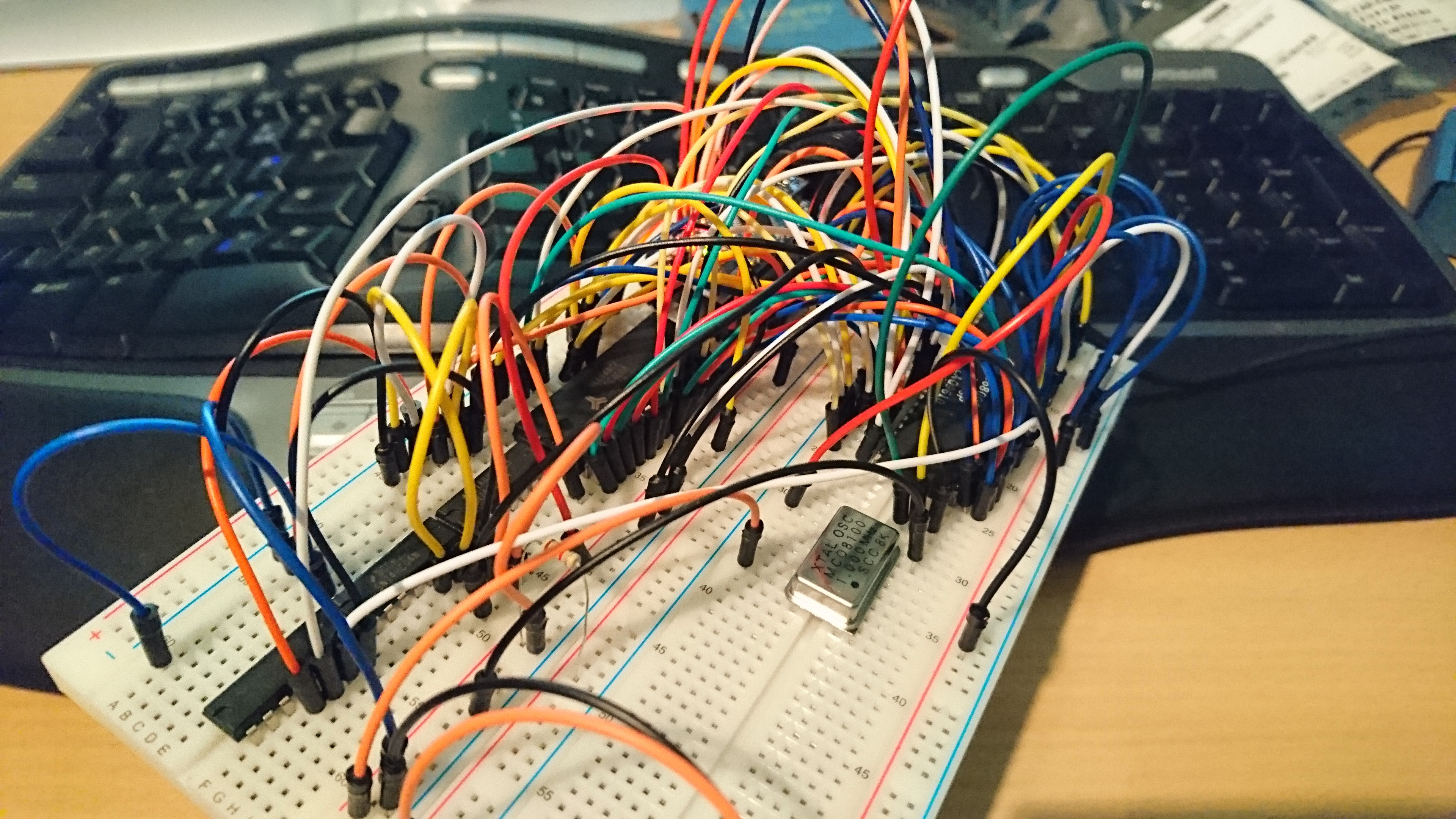
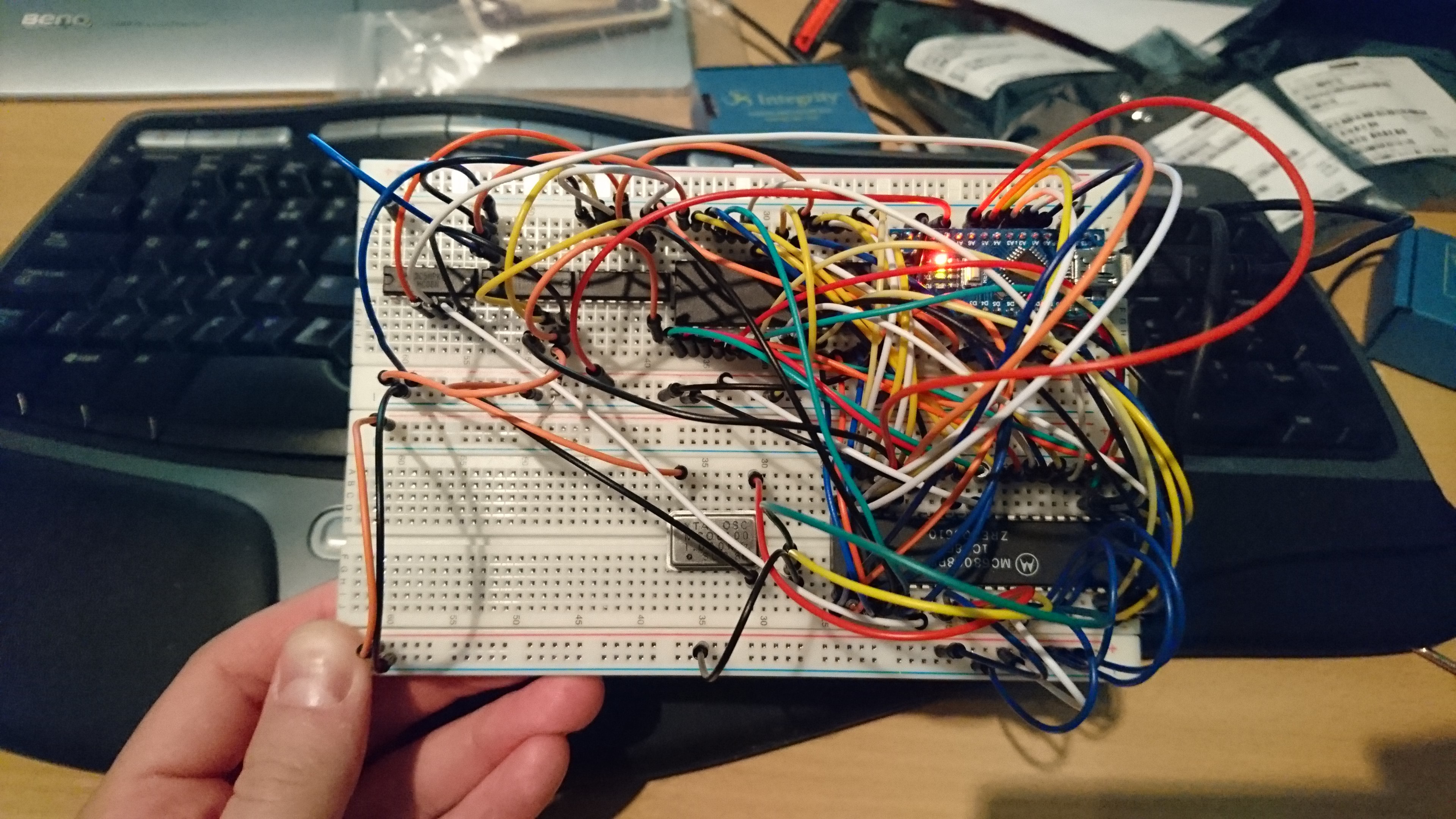
Assuming everything has gone to plan, and you've wired up the circuit as described, you're left with something looking like this!
Along the top row: three 74-series logic gates performing the address decoding, the static RAM and then the Arduino.
Along the bottom row: the quartz crystal oscillator and CPU. Also includes a dreadful reset circuit!

Here's a video of it in motion so you can see the structure.

Discussions
Become a Hackaday.io Member
Create an account to leave a comment. Already have an account? Log In.