Close
0%
0%

Doctor Who working Sonic Screwdriver

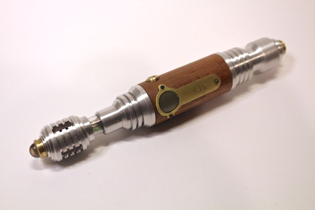
A custom functioning Sonic Screwdriver for my son.

Similar projects worth following
Last Halloween my oldest son Colin dressed up as the Doctor from Doctor Who and I cobbled together a Sonic Screwdriver for him from bits of junk I scrounged up in the garage. Upon seeing the Sonic Screwdriver my youngest son Sam decided he absolutely had to have one. Sam however declared that his screwdriver needed to work- he wanted more than just a cool looking prop.

He wanted a functional Sonic Screwdriver.

The neat thing about this project is you can easily tailor it to include all different kids of sensors to learn about the world around you. Inexpensive accelerometers, altitude sensors, barometric pressure sensors, GPS sensors, etc. are all readily available and you can make a custom Sonic Screwdriver to house whatever sensors you want.


"They're scientific instruments, not water pistols!"

With the War Doctor's words in mind we decided that it would be really neat if Sam's screwdriver could monitor temperature and humidity and save the data to a micro SD card as well as display the temperature via a RGB LED. Sam has two hermit crabs (named Pickles and Sherman) and he thought it would be cool to be able to measure the temperature and humidity of their habitat... He also thought a flashlight function would come in handy (good for reading books under the covers) and of course it had to make a neat sound and have a big blue light on the tip for the "sonic" function. Since we were going to use a photocell to turn on the flashlight it was decided to log that data as well as the pressure on the force sensitive resistor pad that activates the blue light and sound.

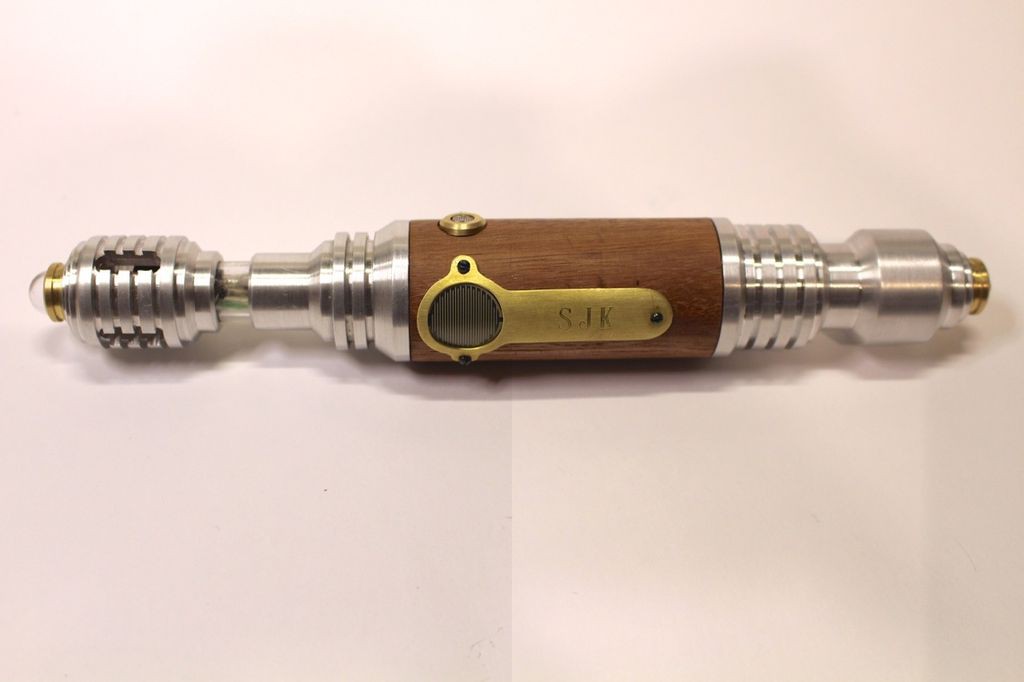
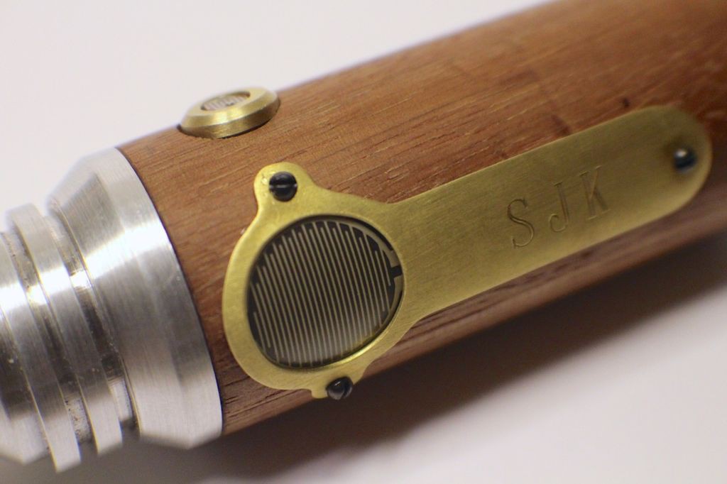
While you could certainly 3d print the screwdriver body (a good option if you don't have access to a lathe) we wanted to make it out of metal- Sam's exact words were "It needs to be metal!" We thought about using a metal tube for the main part of the body but I thought the wood body would look cool and provide a nice contrast to the Aluminum end pieces. I needed a way to hold the force sensitive resistor and photocell in place so I decided to make brass pieces to mount them to the wood body. Turned brass pieces also provided a nice contrast for the LED end caps.

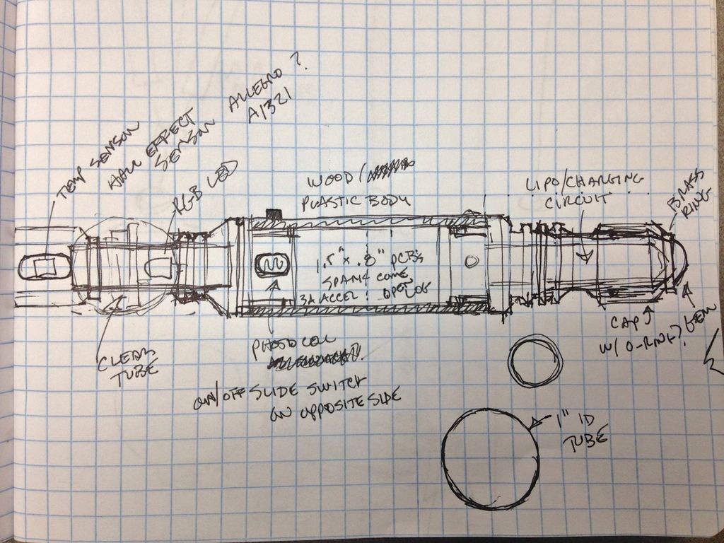
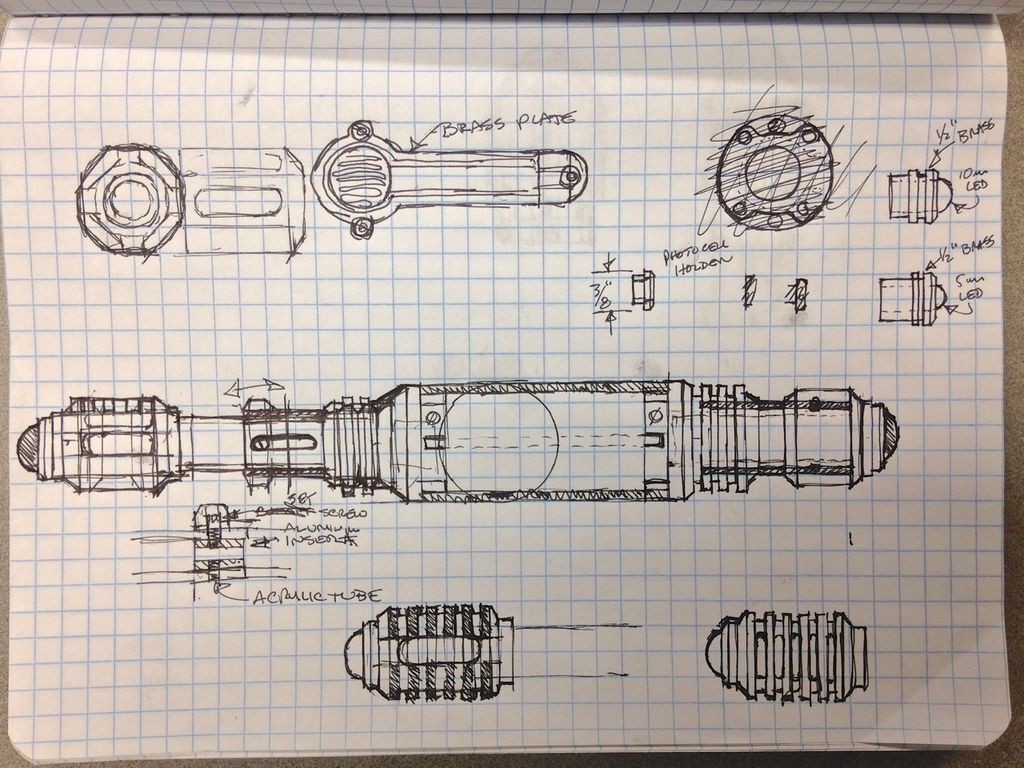
A couple of quick design sketches were made-
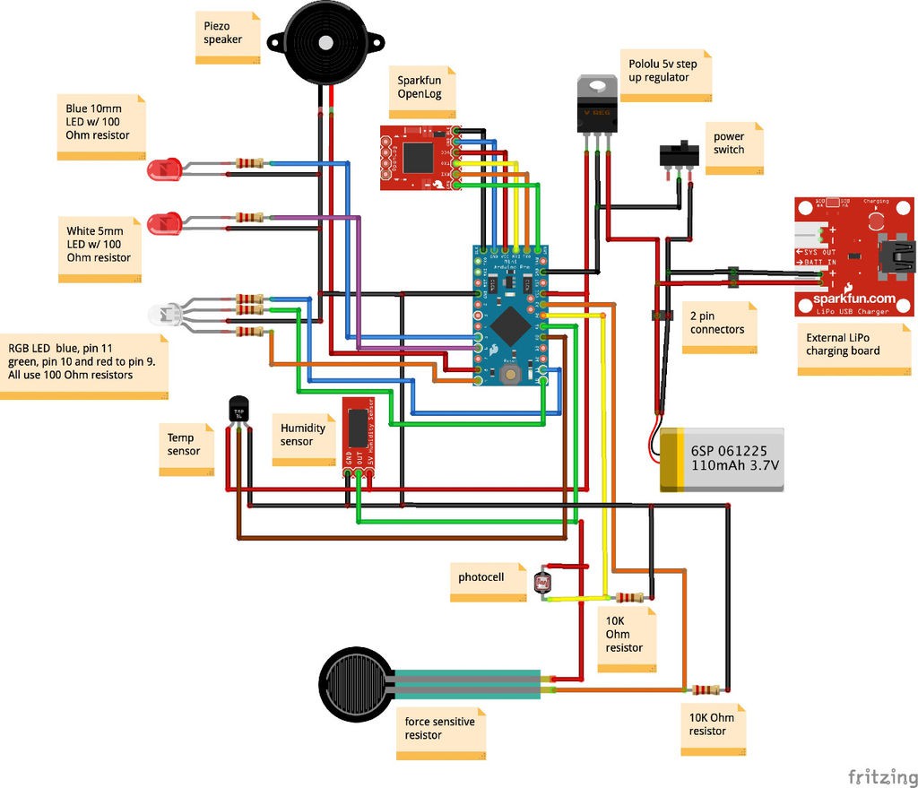
Once we settled on electronics/sensors I made a wiring diagram-
TempHumidityLightFSR.ino

Arduino code for Sonic Screwdriver

ino - 5.33 kB - 02/09/2017 at 06:06

Download

View all 19 components

  • Build Log 5- Finished!

    jeromekelty02/09/2017 at 03:51 1 comment

    Finished!

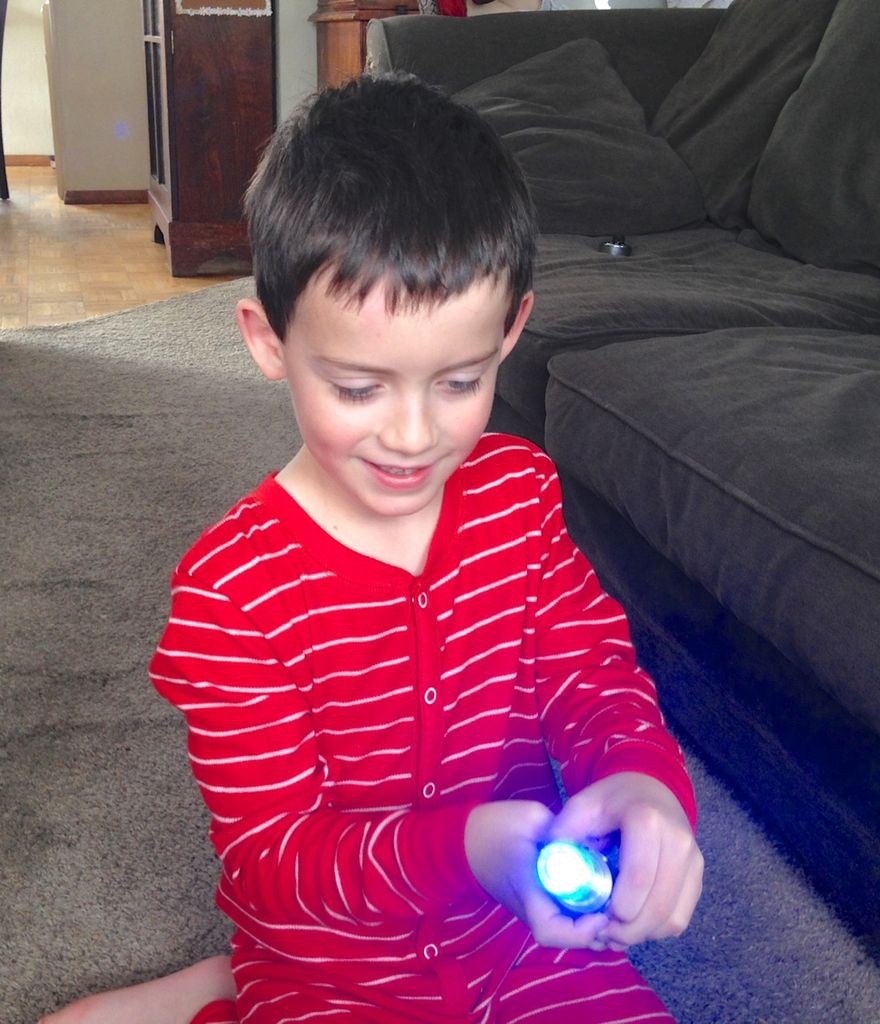
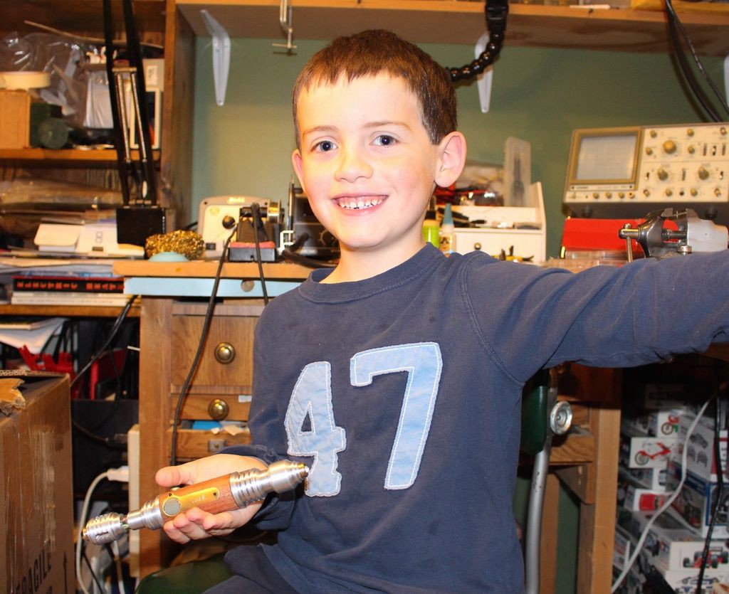
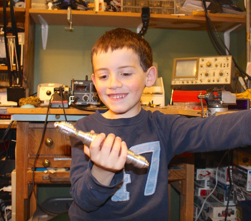
    The young Time Lord inspects his new Sonic Screwdriver!


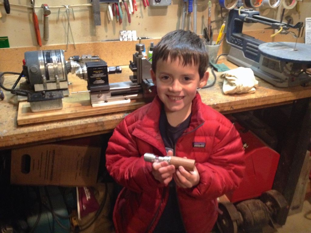
    Once I got everything properly tested and fit together I presented the finished Sonic Screwdriver to Sam and he was absolutely thrilled. He had a lot of fun helping build it - he absolutely loves electronics, building things and working in the garage with me. He already has some ideas for improvements to his screwdriver and we spent some time the other day figuring out how to improve the battery charging process. I am very curious to see how he uses it and how long it takes his brothers to decide they want their own custom screwdrivers!

    Sam testing the flashlight function.

    Testing the "sonic" function.

    That's one happy Time Lord!

    He's already thinking of improvements...

    Helpful construction tips:

    The biggest mistake I made was not thinking about how much space the wiring takes up. I really didn't want to make the screwdriver body any larger than necessary (it needed to be able to be comfortably held by a child) and even after carefully measuring all of the components and doing a lot of test fitting I still ended up rebuilding the circuit in order to make things fit. If I was to do it all over again (and I probably will) I'd make a smaller custom circuit board using as many surface mount components as possible. This would help to shorten wire lengths and really clean things up.

    Test your circuit on a breadboard before beginning construction. Believe me when I say this will help you from ripping your hair out later when doing troubleshooting because something isn't working properly.

    When assembling your circuit use a continuity tester after soldering connections/wires in order to make sure your connections are good and you don't have any shorts in your circuit. See the above comment as to why you want to do this. There's a great multimeter tutorial here.

    I specifically chose to use analog sensors as I find they are a bit easier for beginners to interface with Arduino boards (compared to i2c and 1-wire sensors.) Adafruit has a fantastic series of sensor tutorials on their Learning System.

    Now go forth Time Lords and make your own awesome Sonic Screwdrivers!

    This was a really fun project- there are so many cool sensors available today that I can only imagine what people will come up with when making their own Sonic Screwdrivers. As always if there are any questions or you need help making your custom Sonic Screwdriver please don't hesitate to ask!

  • Build Log 4- Programming and data logging

    jeromekelty02/09/2017 at 03:33 0 comments

    Programming is super simple if you're already familiar with Arduino. Just remove the OpenLog from the connector and connect a FTDI breakout board (or cable) to the header pins on the board to upload your code. When you're finished uploading the code just plug the OpenLog board back into the header. Make sure that your FTDI connector voltage matches that of the Arduino you're using. If you're not familiar with Arduino I wrote up a short guide here that will help you get started.

    If everything loads properly the RGB LED should light up. The LED will change color as the temperature changes- when it's really cold it'll turn bright blue, then shift to green as it warms up and finally to bright red as it gets hot. When the force sensitive resistor is firmly pressed the large blue LED will light up and a tone will play. I kept it to a single tone as the sound effect from the TV show makes my dog go nuts- she hates it and runs away so I couldn't do that. I tried a lot of sounds and this tone didn't seem to bother her. When the photocell is covered by a finger the white LED will light up to full brightness and as more light is available the white LED will dim until it turns off.

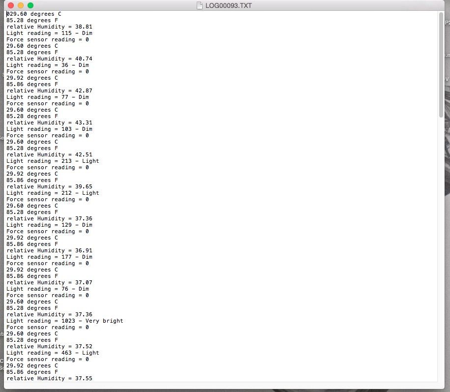
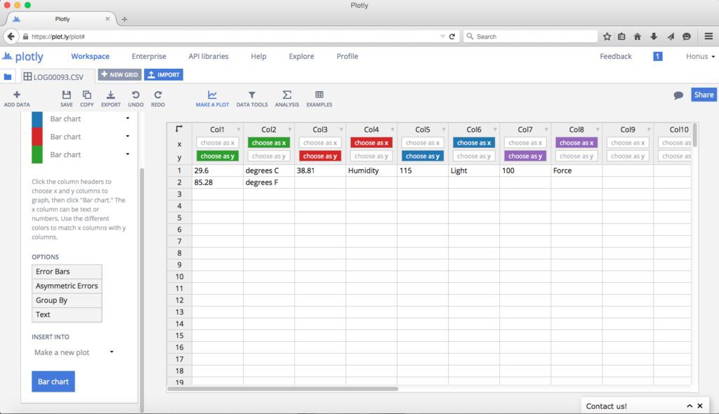
    To obtain the logged sensor data just remove the SD card from the OpenLog and download the .TXT files to your computer. If you want you can export the data to Plotly and make all kinds of cool graphs, make a Google Chart or upload it to the Sparkfun data site.

    There are notes in the code about various connections and how to modify the code if you're using a 3.3V board.

    Sensor readings recorded by the OpenLog.

    Entering logged values in Plotly.

    Plotly allows you to graph data in all sorts of different ways.

    Here's the code-

    //TMP36 Pin Variables
    int sensorPin = 0; //the analog pin the TMP36's Vout (sense) pin is connected to
    //the resolution is 10 mV / degree centigrade with a
    //500 mV offset to allow for negative temperatures
    int sensorVal = 0;

    int HIH4030_Pin = 1; // humidity sensor is connected to analog pin 1
    int photocellPin = 2; // photocell is connected to analog pin 2
    int photocellReading;


    int fsrSensor = 3; // the FSR sensor is connected to analog pin 3
    int threshold = 600; // threshold value to decide when the sensor input triggers
    int ledPin = 5; // blue 10mm LED connected to pin 5


    int fsrReading = 0;


    int redPin = 9; // RGB LED red connected to pin 9
    int greenPin = 10; // RGB LED green connected to pin 10
    int bluePin = 11; // RGB LED blue connected to pin 11
    int whtPin = 6; // white LED connected to pin 6
    int whtbrightness;


    int blueTemp= 0; int greenTemp= 0; int redTemp= 0;


    int speakerPin = 8; // piezo connected to pin 8


    void setup()
    {
    Serial.begin(9600); // Start the serial connection with the computer
    // to view the result open the serial monitor
    Serial.print(millis()); // print time in milliseconds

    pinMode(ledPin, OUTPUT); // sets the blue 10mm LED pin as output
    digitalWrite(ledPin, LOW);
    }

    void loop() // run over and over again
    {
    //getting the voltage reading from the temperature sensor
    int reading = analogRead(sensorPin);

    // converting that reading to voltage, for 3.3v arduino use 3.3
    float voltage = reading * 5.5;
    voltage /= 1024.0;

    // now print out the temperature
    float temperatureC = (voltage - 0.5) * 100 ; //converting from 10 mv per degree with 500 mV offset
    //to degrees ((voltage - 500mV) times 100)
    Serial.print(temperatureC); Serial.println(" degrees C");

    // now convert to Fahrenheit
    float temperatureF = (temperatureC * 9.0 / 5.0) + 32.0;
    Serial.print(temperatureF); Serial.println(" degrees F");

    if(temperatureC<0){
    analogWrite(bluePin, 255);}
    else if(temperatureC>0&&temperatureC<=25){
    blueTemp= map(temperatureC, 0, 25, 255, 0);
    analogWrite(bluePin, blueTemp);}
    else if(temperatureC>25){
    analogWrite(bluePin, 0);}


    if(temperatureC<10){
    analogWrite(greenPin, 0);}
    else if(temperatureC>13&&temperatureC<=30){
    greenTemp = map(temperatureC, 13, 27, 1, 254);
    analogWrite(greenPin, greenTemp);}
    else if(temperatureC>13&&temperatureC<=27){
    greenTemp = map(temperatureC, 13,...

    Read more »

  • Build Log 3- Electronics

    jeromekelty02/09/2017 at 02:28 0 comments

    When designing the electronics for this I wanted to use as many off the shelf parts as possible so anyone could build it and easily modify it. The way the system works is the Arduino reads the sensors and spits out a value to the OpenLog to log it on the micro SD card. The value from the photocell is used to determine the amount of light available and then the white LED lights up accordingly. The force sensor reads finger pressure on the pad and then triggers the blue LED and sound effect. It's really a pretty simple circuit and it's easy to substitute or add all different types of analog sensors. I definitely recommend building the circuit on a breadboard first and running your code in order to make sure everything is working properly.

    While the circuit design is relatively simple building it requires a bit of patience...

    There's a lot of hardware that has to fit in a very small space and soldering all of the point to point connections can be a bit tricky when trying to make everything fit on a small piece of prototyping board. If you have some soldering experience you'll be OK but it's definitely not a job for a beginner.

    I began by soldering the Arduino in place first, followed by the step up voltage regulator. The Arduino Pro Mini I used is the 5V version but the 3.3V version can be used as well- you just need to change two small details in the code (noted in the code) and change how the power from the step up converter is run. On the 5V version the power from the step up converter is connected to Vcc but on the 3.3V Pro Mini it needs to be connected to the Raw pin. That's the only difference so it's pretty easy to adapt it to whatever version you want to use- use whichever version best supports the voltage requirements of the sensors you want to use.

    Once the Pro Mini was soldered in place I soldered in a header for the OpenLog. The OpenLog needs to be removable as the same pins that are used to program the Arduino are the pins used to send data to the OpenLog. On the underside of the board I connected these pins using thin gauge magnet wire in order to save as much space as possible. To protect the thin wires from abrasion (and possibly causing a short) I first put down a small strip of Kapton tape before soldering the wires in place. Once the wires were soldered I put another layer of Kapton tape over the wires. Kapton tape is awesome stuff- it stays put really well and the heat from the soldering iron won't damage it. You can also use it to hold wires in place while soldering, which is pretty handy.

    Assembling the rest of the circuit is pretty straight forward. I tried to use the thinnest, most flexible wire possible in order to save space and reduce wire lengths by combining common power and ground lines. When I first wired up the temperature and humidity sensors with the LED in the nose piece I used wires that were too stiff so I later replaced these wires with some thin ribbon cable. I fully rebuilt this circuit twice in my quest to get everything to fit in the screwdriver body.

    My family bought me a hot air rework station for Christmas this past year and let me tell you they are an awesome tool for taking apart circuits when you need to heat multiple connections at the same time in order to pull things apart. They are also also killer for heating up heat shrink tubing- make sure to use heat shrink on all of the connections to avoid causing a short circuit!

    Once I got the circuit finished I powered it up and tested it out- worked like a charm! I was able to read data from the sensors and everything functioned as it should. Next I carefully stuffed the electronics inside the screwdriver body- and it didn't fit. Again. Darn it!

    As it turned out the wires needed to be a certain length in order to be able to connect everything and be able to pull it apart and they took up too much space in the rear housing section with the USB charging circuit. Fortunately the solution was pretty simple- I just removed the charging circuit and...

    Read more »

  • Build Log 2- Creating the brass details

    jeromekelty02/08/2017 at 07:32 0 comments

    Beauty is in the details...

    The brass details took a lot of time to make but I think they really made for nice accents on the finished piece.

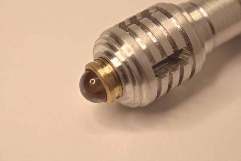
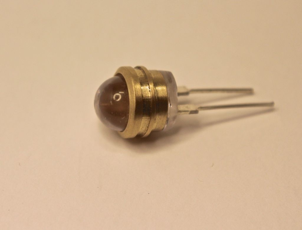
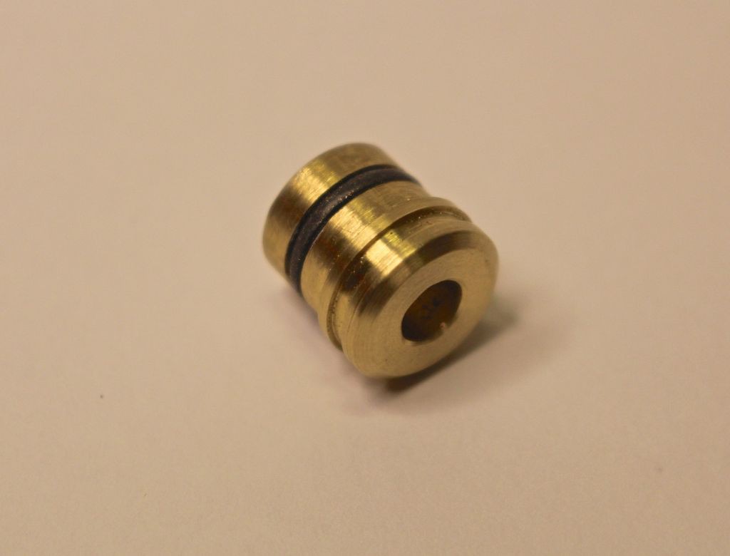
    I began with the holder for the 10mm blue LED that sits in the nose piece. This was turned on the lathe and the LED was glued in place with superglue. The holder for the 5mm white LED at the back end was also turned from brass stock and a groove was cut so an o-ring could be fitted so it could be removed- I did this in anticipation of fitting a charging jack at the end of the screwdriver.

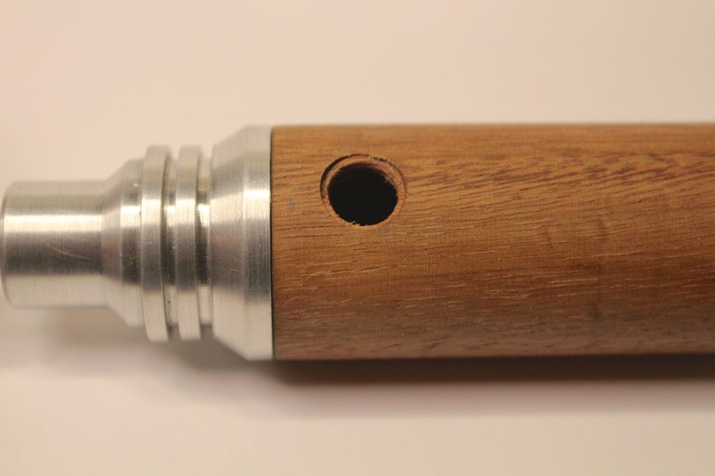
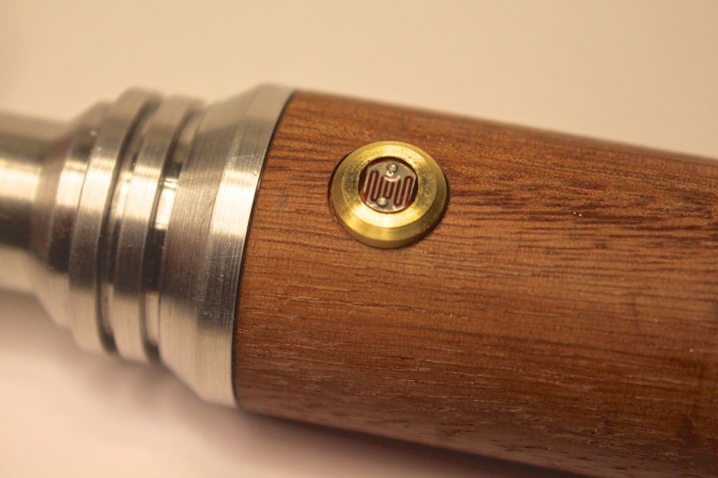
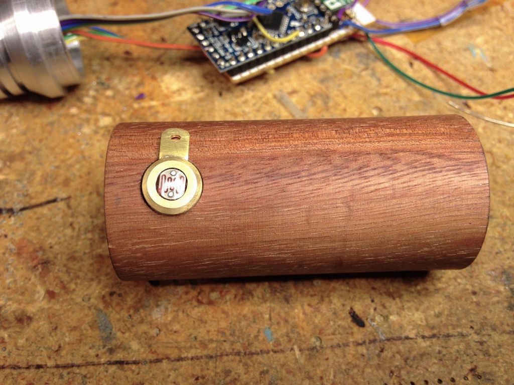
    Next came the brass holder for the photocell. The photocell has an flat oval shape so the center was bored and then an oval slot was milled in the piece using a 3/16" end mill. After test fitting the photocell a 3/8" diameter relief was cut in the wood body using a 3/8" end mill in my drill press so the photocell holder would sit flush on the wood body.

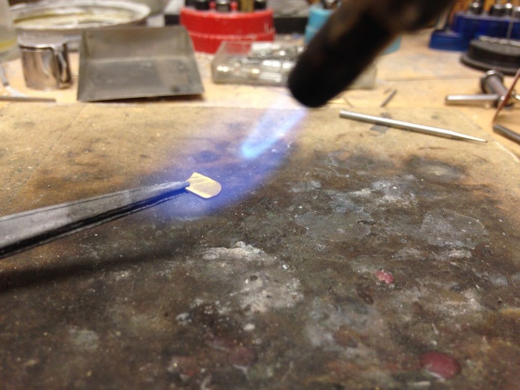
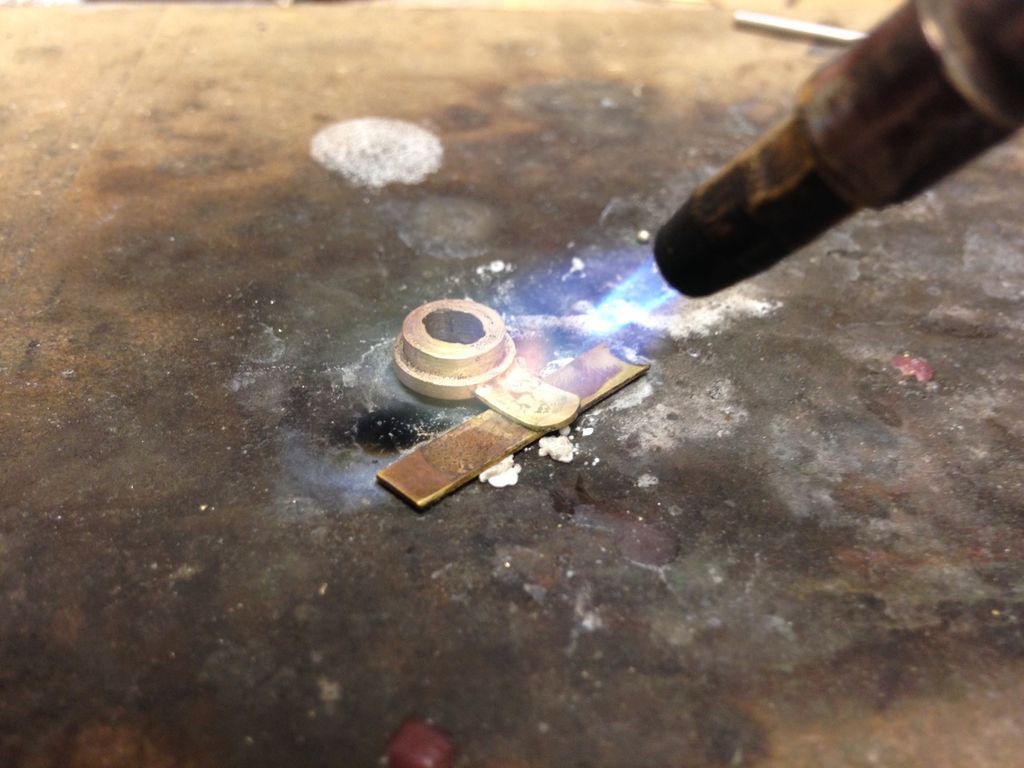
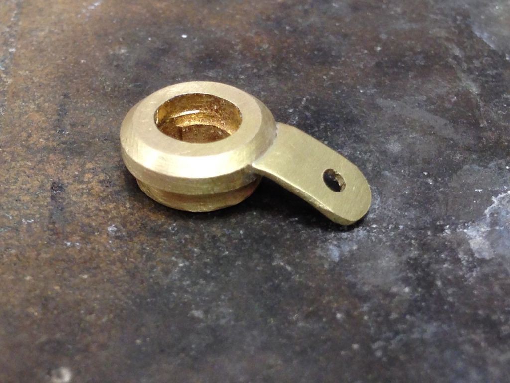
    Once I was happy with the fit I made a mounting tab for the brass photocell body. A small tab was cut, shaped and then annealed with a torch- this makes the metal soft so it's easy to bend to match the curvature of the wood body. This tab was then silver soldered to the photocell holder using a torch.

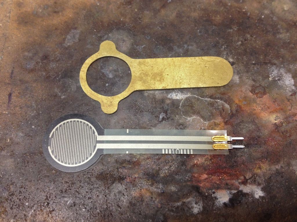
    The cover plate for the force sensitive resistor was cut from brass sheet, annealed with a torch and bent to match the wood body. The resistor has an adhesive backing but I figured there was no way it would properly adhere to the round wood body so the cover plate was devised as a way to hold the resistor in place while leaving the proper exposed round pad area. The ends of the force sensitive resistor slide through a small slot cut in the wood body underneath the cover plate- this makes it easy to attach the resistor to the electronics inside the wood body.

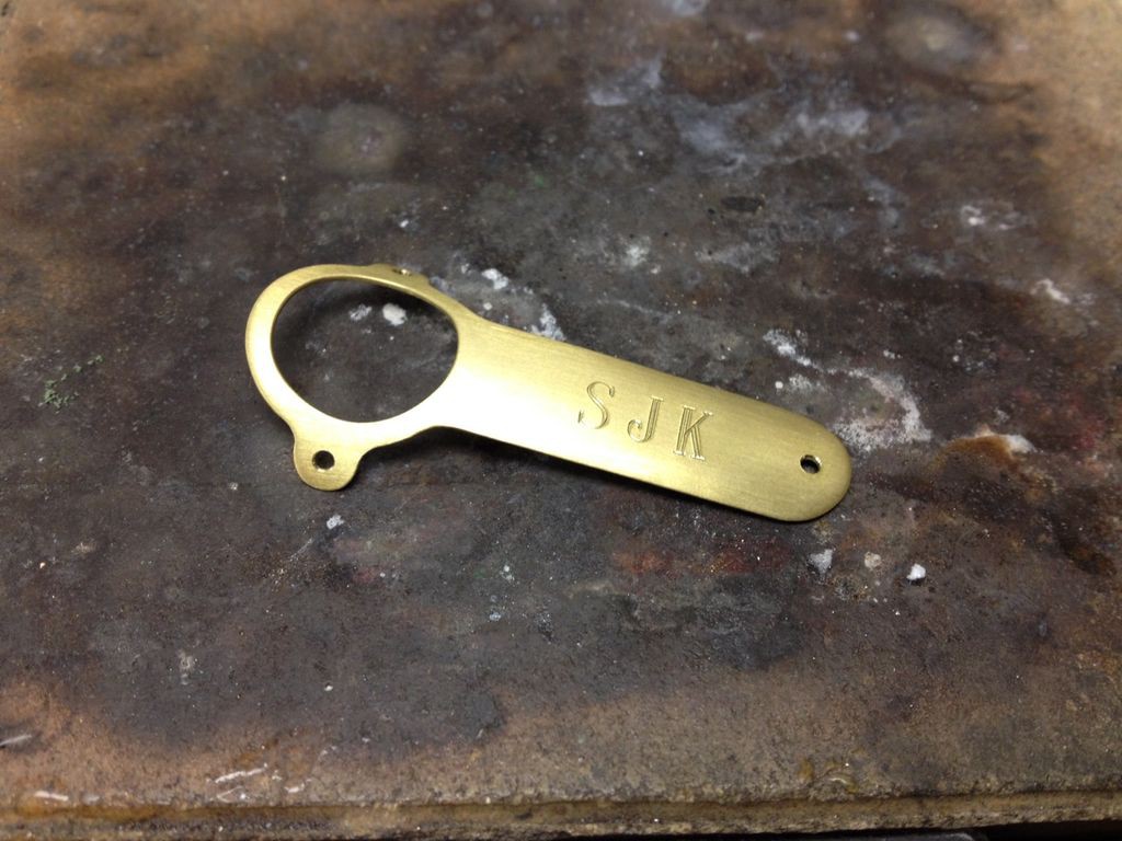
    As a finishing touch I engraved my son's initials in the cover plate using an old pantograph engraving machine at my work. Another option that would be neat would be to hand engrave or chemically etch Gallifreyen symbols on the cover plate.

    After the cover plate and photocell holder were finished I attached them to the wood body using very small wood screws.

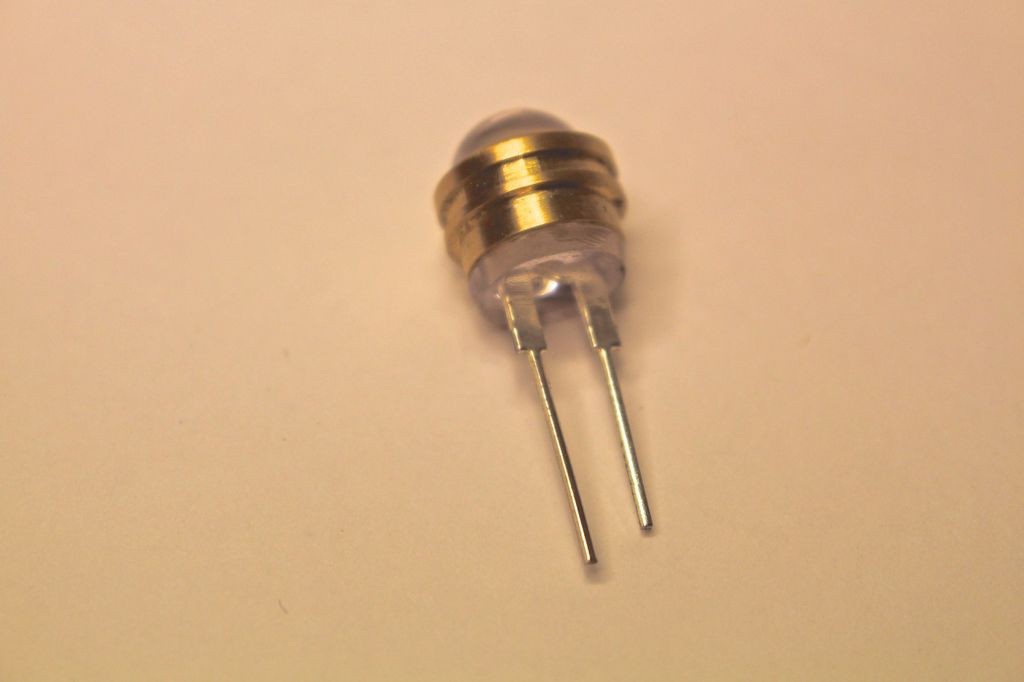
    Here's the brass cap that holds the 10mm blue LED.

    The back of the LED had to be trimmed slightly with a Dremel tool so it didn't extend beyond the diameter of the brass cap.

    The brass cap that holds the 5mm white LED.

    The O-ring sits in a groove and allows the brass cap to be easily removed from the Aluminum end piece. I made this in anticipation of having a charging port (which didn't work out- more on that later.)

    The LED is superglued into the brass cap.

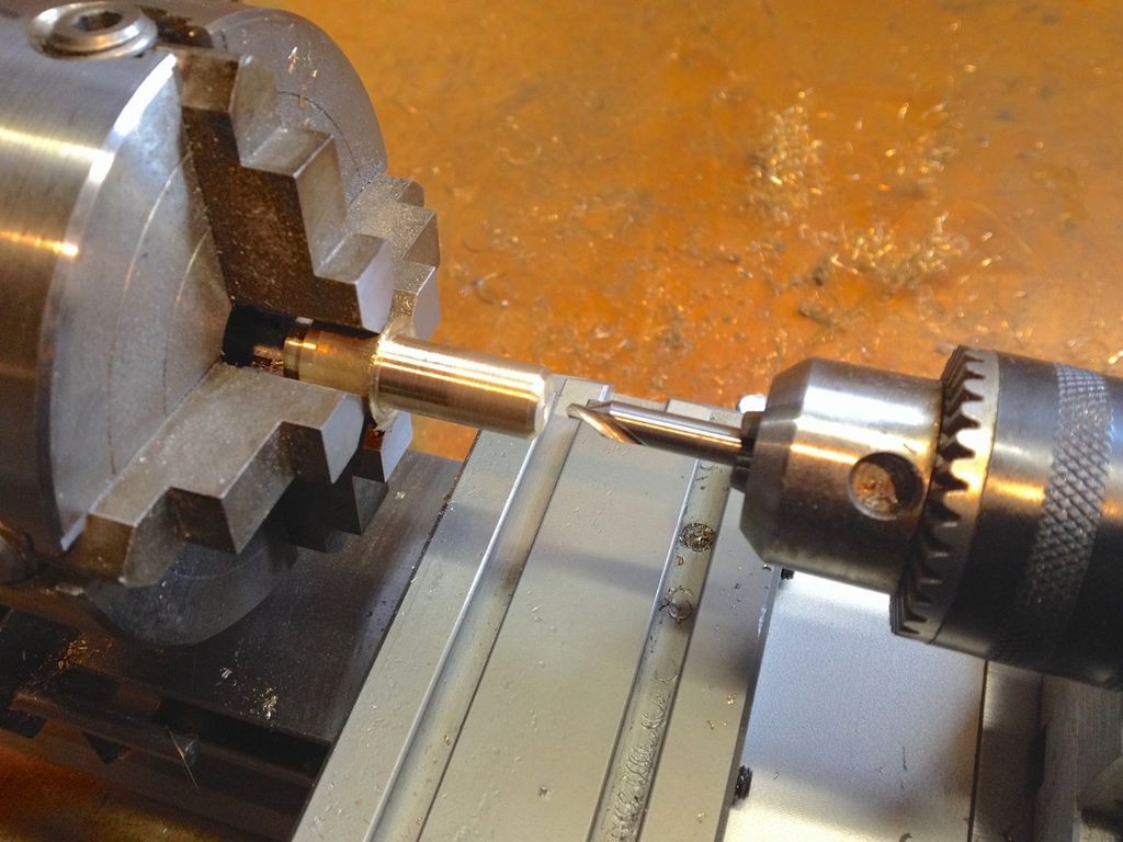
    Making a brass holder for the photocell. Using a center drill to mark the location for drilling the hole for the photocell.

    Milling the oval slot in the brass photocell holder.

    Testing the fit of the photocell.

    A relief was cut in the wood body for the photocell holder. This was done with a flat bottom 3/8" end mill.

    Test fitting the photocell holder in the wood body. Perfect!

    Annealing brass to make it easier to bend. This is for a mounting tab for the photocell holder.

    Soldering the mounting tab to the photocell holder with silver solder.

    The finished tab soldered into place. The hole is for a small wood screw.

    Test fitting the finished photocell holder.

    Cutting out the brass plate for the force sensitive resistor. This was then annealed and bent to shape on the wood screwdriver body.

    Engraving the brass plate with an old pantograph engraving machine.

    The finished curved plate with my son's initials engraved.

    The finished plate with the force sensitive resistor held underneath. The end of the resistor reaches the inside of the wood body through a small slot cut under the plate with a Dremel tool.

  • Build Log 1- Making the housing

    jeromekelty02/08/2017 at 06:56 0 comments

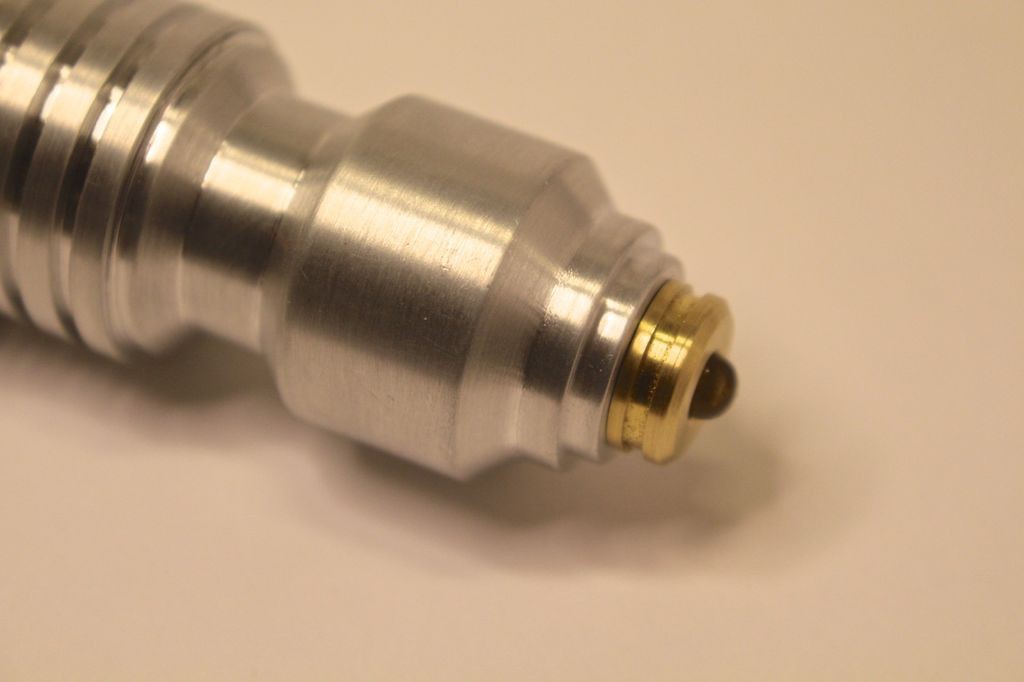
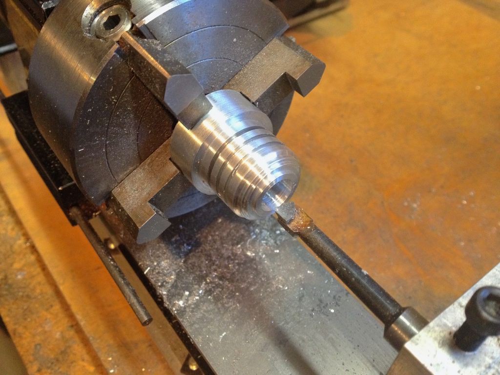
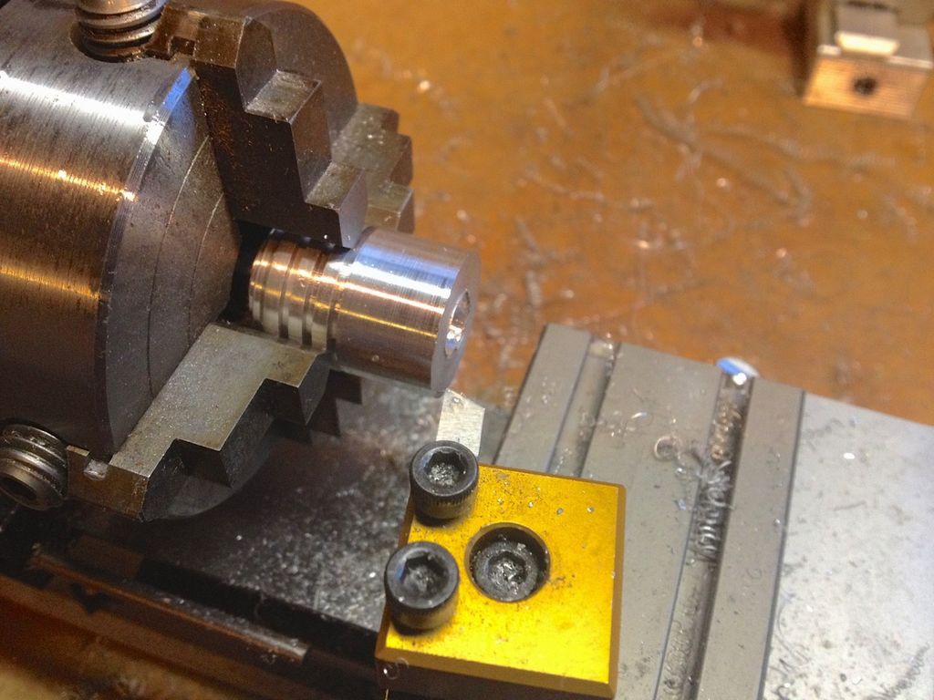
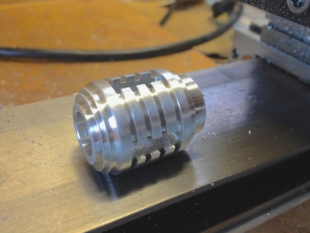
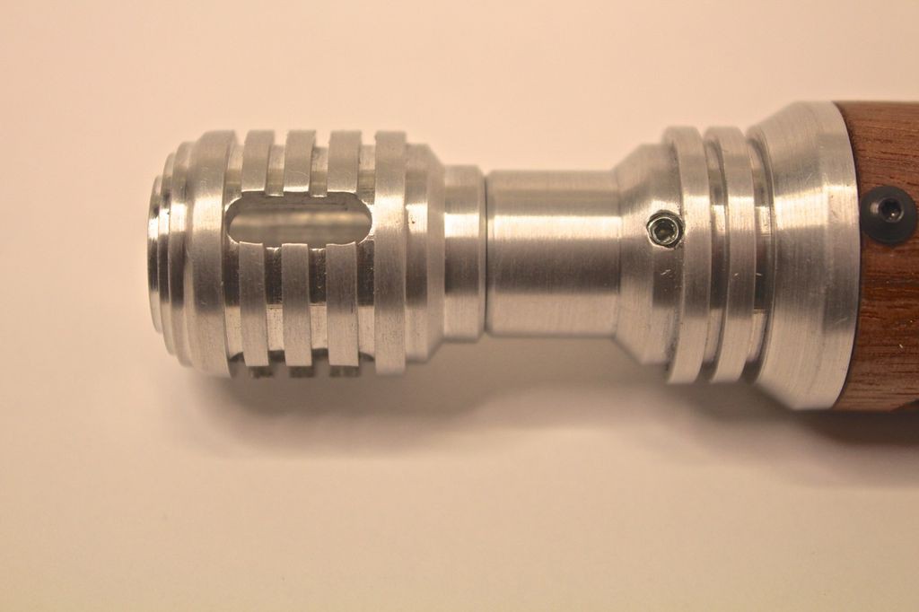
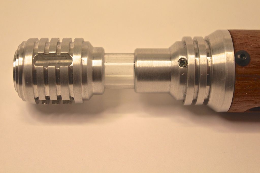
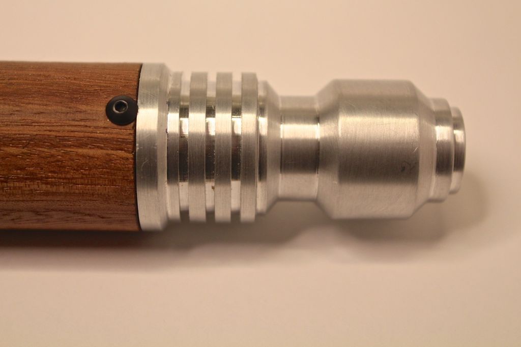
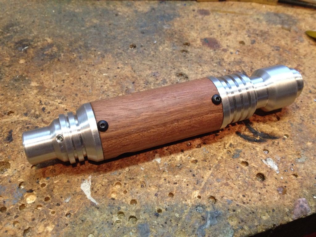
    We made the main body from a section of 1 1/4" hardwood dowel I found in my garage. I bored out the inside to 1" diameter and then turned down the outer diameter. The Aluminum pieces were turned on my lathe. The grooves were cut using a cut off tool and the center holes were drilled and bored out using a boring bar. Four slots were milled in the nose piece using a 3/16" end mill- these slots allow air to circulate around the sensors placed in the nose piece. A 1/2" diameter hole was bored in the front body piece and nose piece so a clear acrylic tube could be fitted. The acrylic tube has a slot cut in it so it can extend and retract- a small set screw in the front body piece locates the slot in the acrylic tube.

    The rear body piece was turned in a similar manner as the front piece and it was hollowed out using a boring bar. Both Aluminum body pieces were then drilled and tapped so they could be held onto the wood center body with a couple of small button head screws. After all of the parts were test fitted they were given a brushed finish using a scotchbrite pad. Finally the acrylic tube was glued into the nose piece with super glue.

    All of the parts were machined on my small benchtop Taig lathe. Sam and I spent many, many weekend hours out in the garage making these parts and he had a blast helping out!

    Here's the finished main body assembly. The Aluminum end pieces are held in place with 4-40 button head screws.

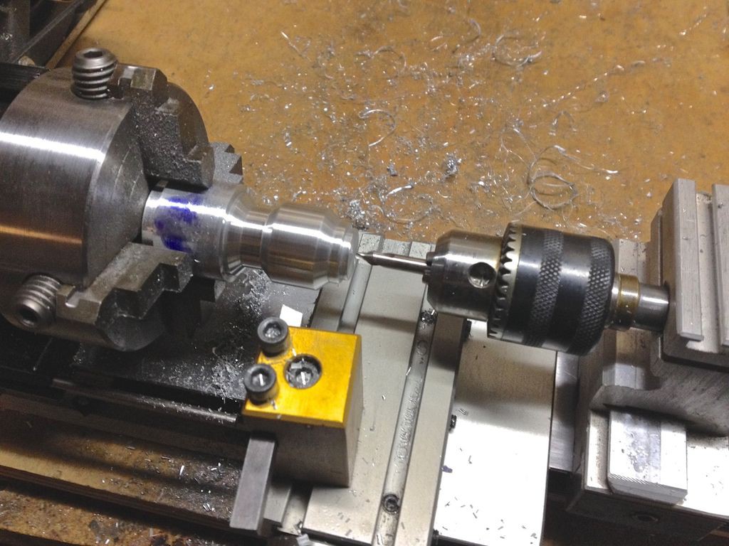
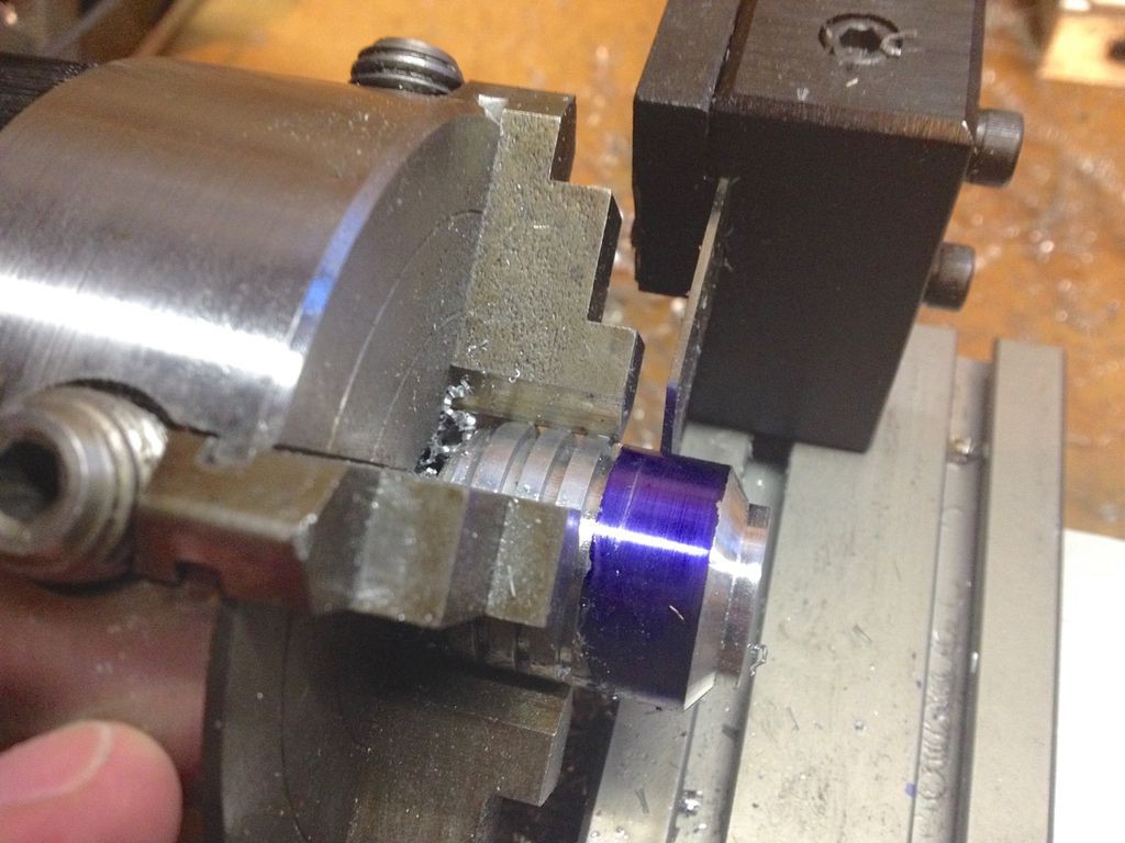
    The Alumium end pieces were turned from solid Aluminum round stock. This shows a cut off tool being used to cut grooves in the Aluminum end pieces. The blue dye (Dykem) allows for the marking of scribe lines for cutting.

    Boring out the nose piece to fit temperature and humidity sensors.

    Turning the nose piece on the lathe. A four jaw chuck allows for very precise centering.

    The finished nose piece after milling 3/16" slots with the lathe milling attachment.

    Here you can see the 3/16" endmill held in a ER16 collet on the lathe.

    Using a center drill to begin the process of boring out the Aluminum rear end piece.

    The nose piece with the 1/2" diameter Acrylic tube glued in place. The slot in the tube is for a locating set screw.

    This shows the nose piece fully retracted. The small 4-40 set screw extends into the slot in the Acrylic tube and allows the tube to slide in and out and not fall out.

    The nose piece fully extended.

    A 4-40 button head screw threads into the Aluminum end piece to hold it in place. If I were to do this again I'd probably make an Aluminum inserts bonded into each end of the wood tube and then slide the end pieces into them. It would be much more secure and more durable.

    Sam helping machine parts in the garage. He'd probably spend the majority of his day in the garage if he could!

View all 5 project logs

  • 1
    Step 1

    Build notes:

    There are basically two ways you can build this- design the body first and then see how great a challenge it is to cram all of the electronics in there or build your electronics and then design the body around them. I sort of took the first approach because I had a very specific look and feel I wanted in the finished piece. It was designed with the sensors and electronics I wanted to use in mind but I had to come up with alternate solutions as I built it due to space limitations. If I had to do it again I'd probably make it even slimmer and do all custom electronics to get everything to fit properly- maybe even add more sensors.

    The method by which the end pieces are secured to the wood tube body is OK but could be a lot better. I'd make an insert and glue it into the wood body and have the ends either press fit or thread into them. It would be much more secure and look a lot cleaner.

    I'd try to figure out a method for removing the SD card without taking the electronics out or have it work over WiFi. Removing the SD card as it is now is a bit of a hassle- my son can't do it by himself. A charging port would also be nice.

View all instructions

Enjoy this project?

Share

Discussions

Mark Smith wrote 02/12/2017 at 23:13 point

This is amazing, I'm really impressed with both the custom construction and the electronics coming together in this small form factor!

Would it be possible to replace the open logger with a similar sized wifi board and have it push out it's readings that way, or would that blow the power budget?

  Are you sure? yes | no

jeromekelty wrote 02/12/2017 at 23:22 point
Thanks so much! Yep, there's no reason why you couldn't do that. One of the ESP8266 boards or a Particle Photon would do the job. It wouldn't run as long with WiFi on but I think the Photon supports a deep sleep mode.

  Are you sure? yes | no

trevorjtclarke wrote 02/09/2017 at 18:24 point

Wow, this is incredible. The details make it far better than any prop. Excellent work.

  Are you sure? yes | no

jeromekelty wrote 02/11/2017 at 15:46 point
Thanks!

  Are you sure? yes | no

Tom Van den Bon wrote 02/08/2017 at 15:46 point

This is beautiful, well done :)

  Are you sure? yes | no

jeromekelty wrote 02/09/2017 at 02:30 point
Thank you sir!

  Are you sure? yes | no

Similar Projects

Does this project spark your interest?

Become a member to follow this project and never miss any updates