 THowden-Capstone
Constraints of the Project
As mentioned in our previous post, this project contains many constraints outlined by the FIRST Robotics Competition rulebook. These constraints define aspects of competition-ready robots, including weight, height, perimeter, electrical components and capabilities, and damage prevention. The constraints that will play an important part in our design of the EverySwerve module have been outlined below.
Table 1: FRC Constraints
| Constraint | Value | Source |
| Number of Propulsion Motors | No more than 4 | FRC Game Manual R502 |
| Maximum Current | 270A for 5 seconds
120A for 500 seconds | MK ES17-12 data sheet am-0282 data sheet |
| Maximum Weight | No greater than 125 lbs. | FRC Game Manual R103 |
| Maximum Frame Perimeter | No greater than 120 in. | FRC Game Manual R101 |
| Battery | No more than 1 12V 18.4 Ah SLA Battery | FRC Game Manual R601 |
| Wire and Breaker Size | 40A breaker, no smaller than 12 AWG Wire
30A breaker, no smaller than 14 AWG Wire 20A breaker, no smaller than 18 AWG Wire | FRC Game Manual R622 |
| Field Damage | Traction devices which damage the competition field are not allowed | FRC Game Manual R201 and R202 |
One of the challenges of pursuing a cheaper, and higher performing KoP drivetrain is finding motors that are both FIRST compliant and perform at the desired level. With this in consideration, motors not currently approved may be required to achieve the goals of this design project. As most of the constraints provided by FRC are basic safety restrictions with avenues to get new components approved, we do not foresee this being a major issue. Another challenge arising from motor selection is the potential for high current, high weight options that cause our design to infringe on the set limitations. For this reason, we plan to heavily analyze every motor we consider to ensure it aligns with our constraints.
Benchmarking Current Solutions
To understand the key physical challenges in the design of EverySwerve, benchmarking of existing solutions must take place. The benchmarking of the two existing drivetrains will provide many key performance metrics that will inform decisions when selecting components for the design. To facilitate the selection of COTS components, reference design parameters will be selected based on calculations of the required physical parameters and use of component data sheets. For motor selection, calculations will determine a torque generated based on the physical parameters of the motor. For a single phase in a brushless DC motor, the static torque is described by:
Where N is the number of turns in a motor winding, B is the magnetic flux density (a known value common to magnets used in inexpensive brushless DC motors), Y is the length of the stator, i is the current through the phase winding (for which a limit is defined by constraints), and D is the diameter of the stator. The desired torque value will be determined by comparison to the benchmark drivetrains as well as a desired acceleration of a complete drivetrain (F = m*a, τ = I*α) to meet benchmark test values. The values of N, Y, and D will be iterated upon to determine approximate motor parameters, which will be used in the search for an appropriate COTS motor. Some COTS motor suppliers will specify these physical parameters or provide motor curves which display the performance characteristics, but many will supply very limited data. In the design team’s experience in procuring COTS motors, inexpensive options are often marketed as for a specific application; i.e. “electric scooter motor” with only a specified voltage, top speed, and current draw. Since a major goal of the design team is to keep the cost low, products that do not have precisely specified performance parameters must be considered, facilitated by simplified analysis such as the calculation explained above and extrapolation/interpolation from available specs. If it is supplied, as it is for all currently FRC-legal motors, the motor curve data will be used to calculate expected performance. The motor curve data for the KoP-staple CIM motor is shown in Figure 1.
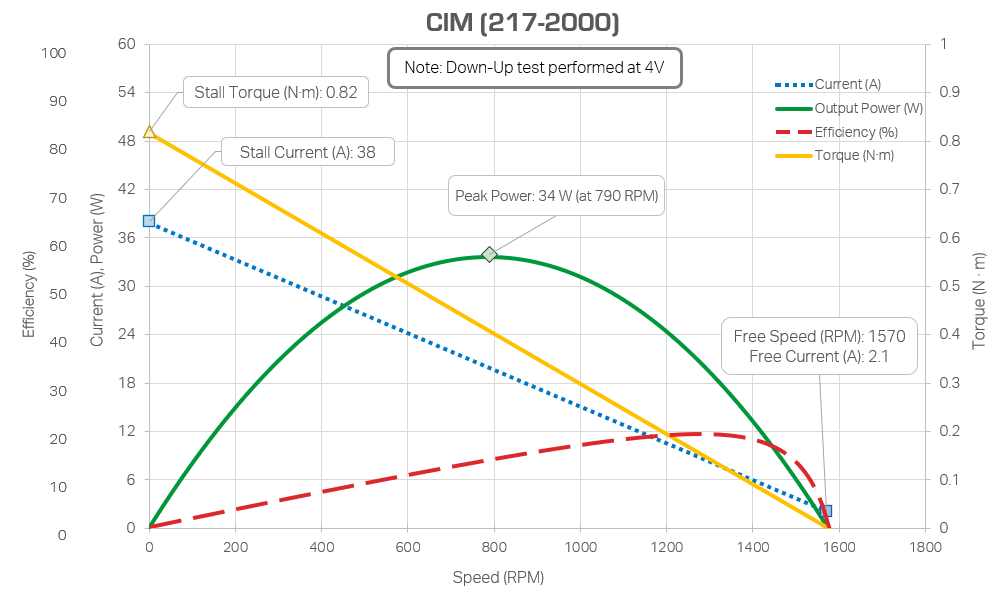
Figure 1: CIM Motor curve diagram
A similar process will be used to select other components such as gears and bearings, though most of those components have simpler parameters. Both will be selected based on their static load ratings in relation to team-generated free body diagrams of theoretically rigid subassemblies. Depending on the application, dynamic load ratings and lifetime may be calculated for some bearings and gears but neglected on others for which the cycle count is expected to be low.
Additional analysis will be performed to ensure the choices made during the design phase do not need critical reconsideration. Structural analysis on custom components that are expected to develop stresses near their allowable limit and of any bolted joints will predict failures and allow for iteration before manufacturing commitments. Based on the determined actuator layout, heat transfer analysis will be performed to ensure that the thermal limits of neighboring materials are not reached. As analysis is performed, problems with the design may arise and after revisions, analysis will be performed again.
Design Challenges
The team has identified two key challenges that will require special consideration in the design, manufacturing, and testing of the EverySwerve module. Some specific challenges that we expect include thinking about the end user and ensuring that components are easy to assemble. The experience level of teams worldwide is highly variable, evident by the distribution of teams across (Figure 2), and assumptions can cause end users with less experience to be left confused. To address this, assembly instructions will be created and comparing the number of steps, components, expected execution times, and unique tools required will be used to compare projected performance to existing solutions. Another challenge is the scalability of the EverySwerve to be included in the KoP in the future. Costs required to develop the EverySwerve will be vastly different from costs to mass produce each unit. Creating an accurate “scaled” BOM will be difficult and subject to change based on economic variables. To address this the team is working to keep part count low, use primarily COTS parts, and develop a highly competitive product.
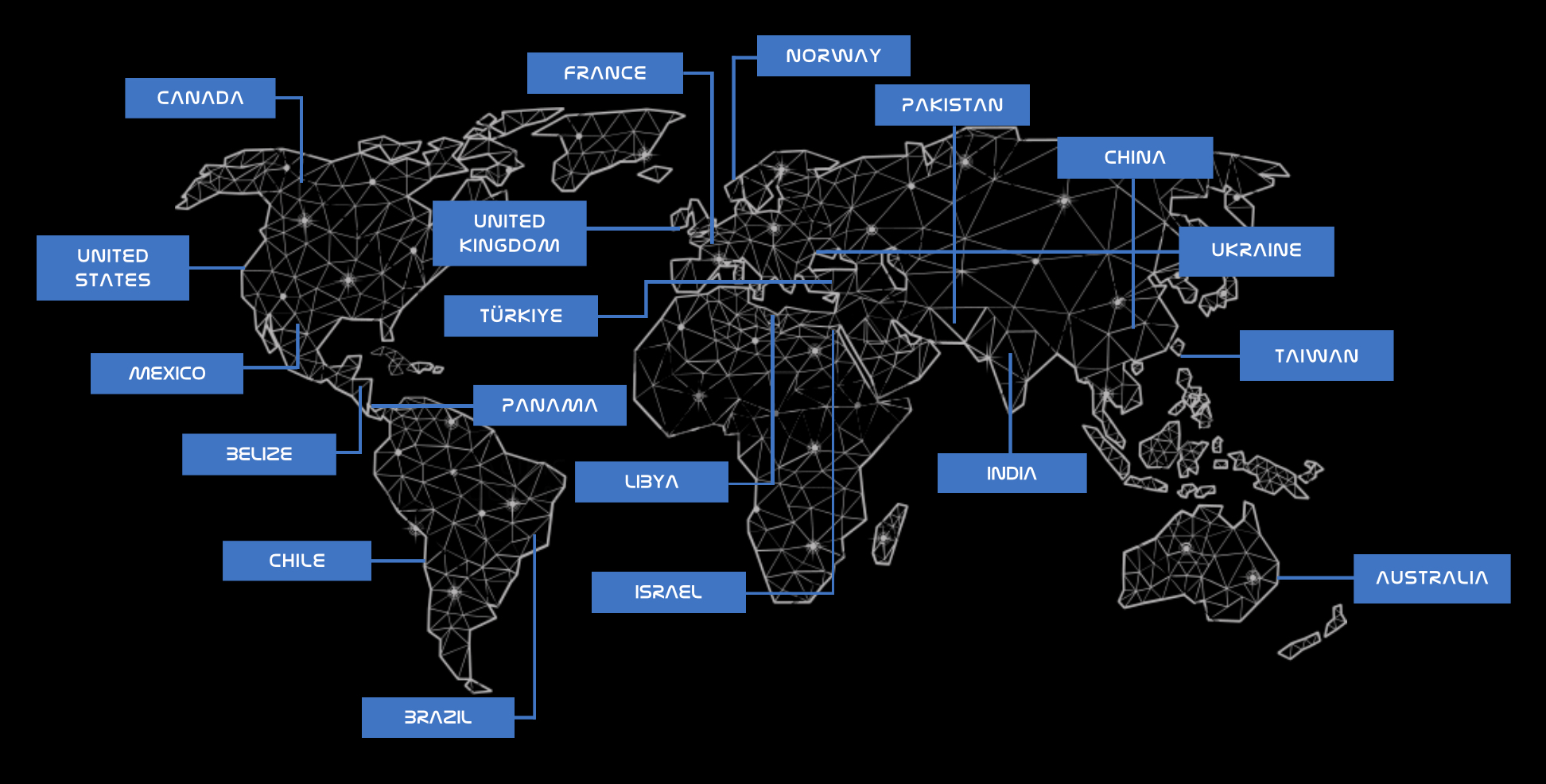
Figure 2: Map of places where EveryBot was used in 2024.
Discussions
Become a Hackaday.io Member
Create an account to leave a comment. Already have an account? Log In.