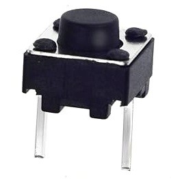
I turned my attention to the Trekulator keypad. My plan is to design a PCB with a pretty standard 4 row by 5 column matrix requiring a total of 9 IO pins to read. I had a bunch of 12 mm x 12 mm push button switches left over from my CHESSmate project that I could use. Here is what one looked like.
Since the keycaps for the buttons have one correct orientation, and given the round protruding knob, I wondered how I could lock the keycap to that position. I could glue it in place but for me glue is a last resort. This is one idea that I came up with.
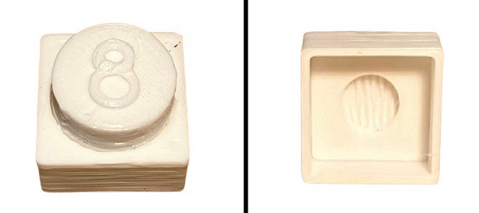
The square base slipped over the base of the switch with enough clearance to shift up and down as the button was pressed but locking the keycap to the correct orientation. While this would have worked it felt a little kludgy to me. The keycap had to be printed in two parts and glued together (ugh) and it just didn't look right.
I hit up DigiKey and found the following.
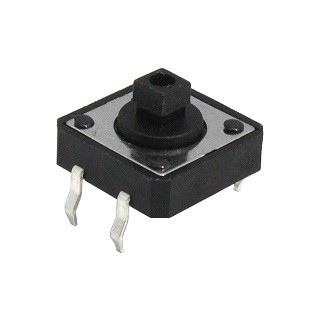
The square knob solves the orientation issue leading to a much simpler keycap.
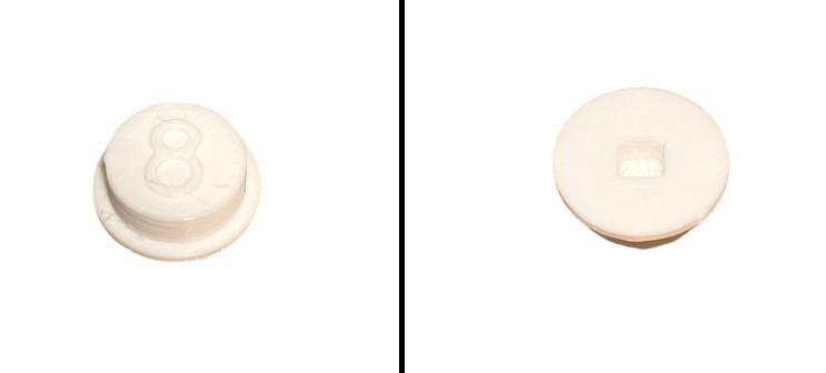
Much better. I guess the lesson learned here is that you shouldn't necessarily force a design just because you have some parts on hand. Sometimes spending a few extra bucks is the way to go.
Just for fun I grabbed a standard protoboard and laid out 20 switches in a 4 x 5 grid. To my surprise the buttons aligned perfectly with holes in the Trekulator (on 18 mm centers). So I made a set of Trekulator keycaps to try it out.
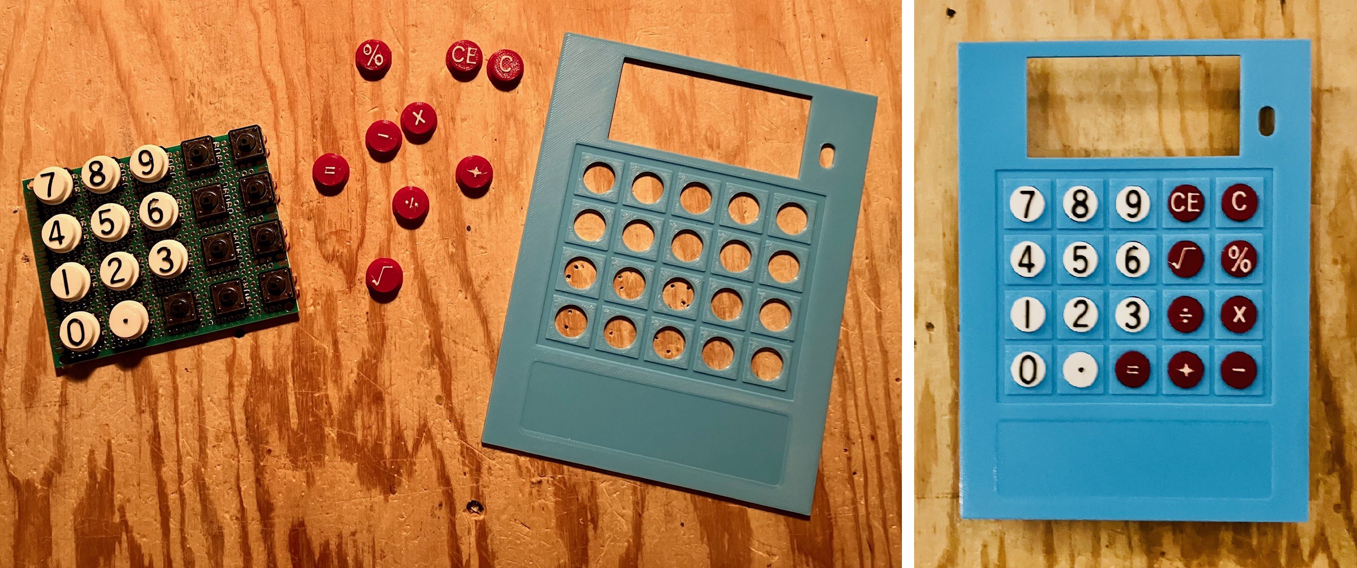
The switches are just set into the protoboard not soldered. I wanted to check how everything fit together, nicely I must say. The buttons work great and have a nice feel, better than the membrane keypad on the original. For a second I considered wiring the keypad point to point as is on the protoboard, but ultimately decided to proceed with a custom keypad PCB which is what I will work on next.
CORRECTION: While I was laying out the keypad PCB I realized that this "coincidental" alignment was not quite true. The protoboard through holes are 2.54 mm apart. The buttons on the original Trekulator are in fact on 18 mm centers. With standard spacing the closest that you can get to 18 mm centers is 17.78 mm (2.54 mm x 7). Close enough that the buttons line up pretty well but not perfectly. I suspect that they worked as well as they did because the switches were not soldered in and thus had a some "flexibility" when pushing through the case holes. I corrected this alignment issue in the PCB.
 Michael Gardi
Discussions
Become a Hackaday.io Member
Create an account to leave a comment. Already have an account? Log In.