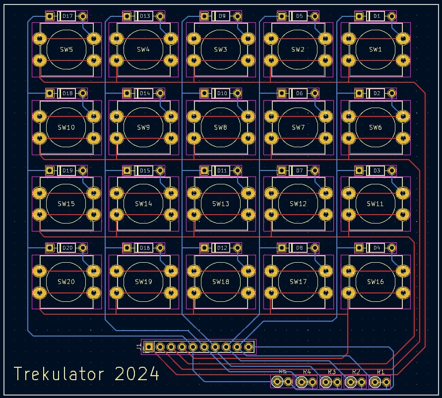
The PCBs for the Trekulator keypad arrived this week. They look pretty good.

So I populated a PCB with switches, diodes, and headers. When I wired it up to the ESP32 I realized that I had a small issue.
The ESP32 has 40 GPIO pins, however only 22 of those pins are available as "unencumbered" INPUTS and 19 as OUTPUTs. By unencumbered I mean can be used without fear of clashing with special purpose functions like SPI flash, Rx, and Tx. Furthermore, of the INPUTS, only 10 have internal pull-ups and 7 have internal pull-downs (supposedly). So in general you have to be very careful when selecting IO pin usage on an ESP32. More so than in the Arduino world.
My Trekulator keypad PCB was designed with no external pull-down resistors because I had assumed that I would use MCU's internal pull-downs. In addition to the lack of IO pins with pull-downs I was having problems using pins that were supposed to have internal pull-downs. So in the end I decided to add external 10K pull-down resistors on the column lines of the matrix. Worked great. You can see in the rightmost image above where I bodged five 10K resistors to the column lines and tied them to ground. I have updated the KiCad design to include the resistors,

With all of the pieces in place I did an integration test.
Now all I have to do is figure out how to get all of this stuff to fit into the Trekulator case, and oh ya, write a calculator program. No problem.
 Michael Gardi
Discussions
Become a Hackaday.io Member
Create an account to leave a comment. Already have an account? Log In.