After having a wonderful moment unpacking the PCBs, I still had to wait for the LEDs to be delivered. This weekend though, they finally arrived.
So I quickly soldered the LEDs very carefully and the Attiny202 onto the board with some capacitors. First realisation was, that the regular neopixel Arduino code is way too big. There's an example of a static tinymegacore library, that worked though.
The footprint of the LED I made myself, so naturally I forgot to check what the schematics symbole looked like. Here I mixed up two pins, which meant the LEDs had no chance of shining.

Secondly, I used the programming pin as the LED data pin, something I corrected in the second version. For testing the code I've added 4 regular WS2812B LEDs on a string instead, to see if the code would work on a different pin as expected. Not sure why the CH340E USB-C programmer wouldn't work for serialUPDI, but I still had an FTDI dongle somewhere and that worked just fine to program the attiny.
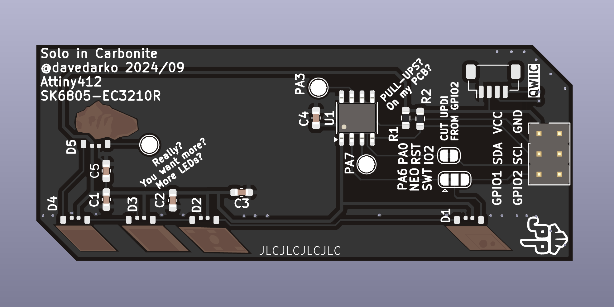
Recently I've been contacted by JLCPCB and they offered to sponser a small run of PCBs and I think this is a great opportunity for this boards second run. The Attiny202 seemed too busy with just the neopixels already, and to keep things open for I2C communication, I have replaced the Attiny202 chip with an Attiny412.
Fixing some labels, adding one more LED, Pullup resistors for I2C, some test points and a qwiic connector, I think I'm happy with the board design.

 davedarko
Discussions
Become a Hackaday.io Member
Create an account to leave a comment. Already have an account? Log In.