 TripleL Robotics
Project Overview
This project aims to create an embedded AI module running a Linux system, combined with a camera, primarily focusing on AI vision applications. The module is divided into two parts: the main control core board and the peripheral board.
What main control chip or circuit is used? --------- Materials
Core board basic composition: The main controller uses Allwinner H6 (1.8GHZ, V200-AI), memory uses Samsung K4E6E304E series LPDDR3 (2GB), plus Samsung EMMC (8GB) and power management chip AXP805, as well as related resistors, capacitors, and inductors. The core board uses a golden finger interface to connect with the peripheral board.
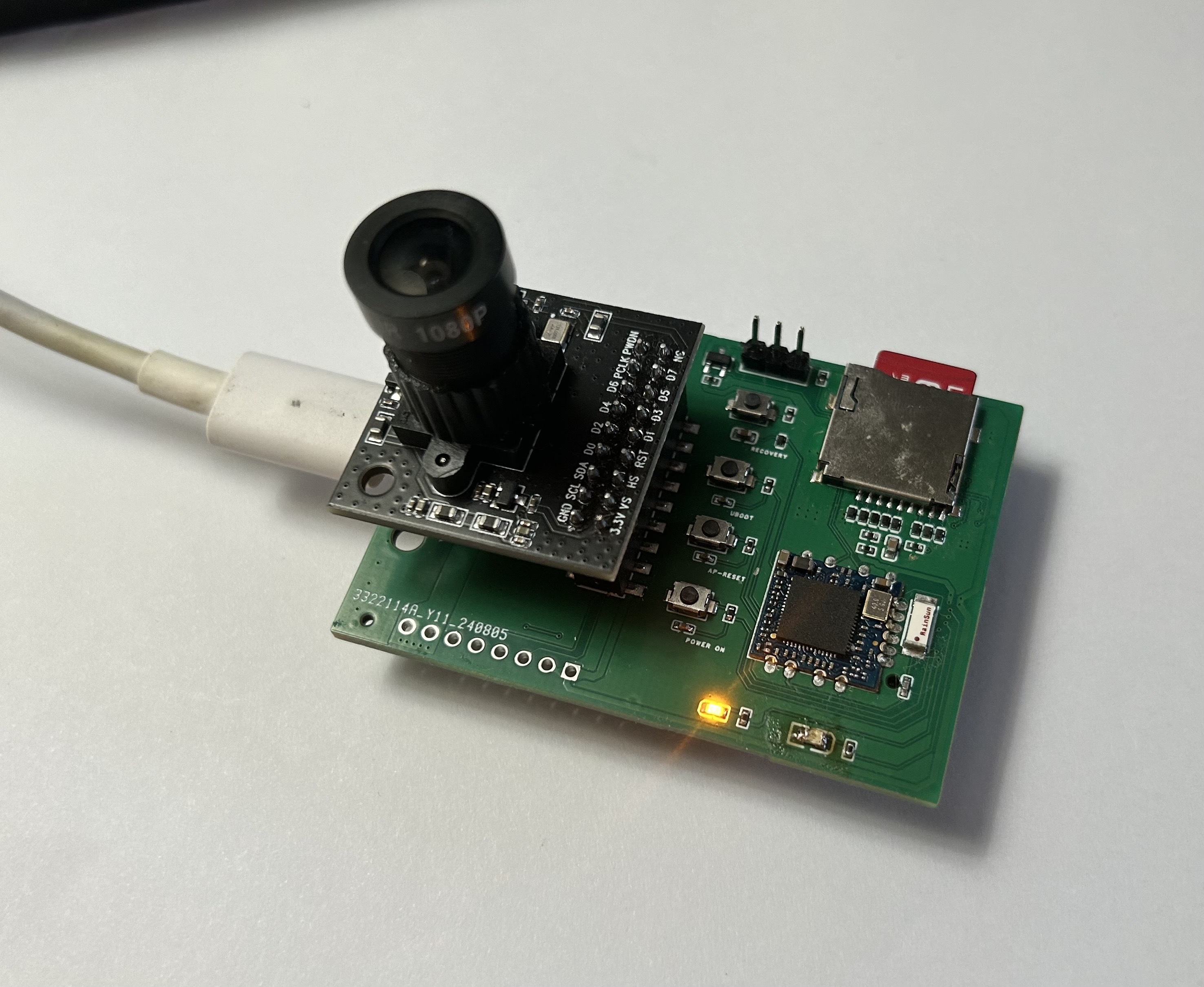
The basic composition of the peripheral board: USB TYPE-C power supply for the core board and peripheral board, related DC-DC step-down modules, several control buttons, wifi module (currently using RTL-8723BU, planning to switch to MT series later), TF card slot, OV5640 camera module. A TPU module (4TOPS) will be added later for AI computation acceleration.
What has been created? -------------------------- Product
By combining the core board and peripheral board, this project can serve as an edge AI processor, running a Linux Sunxi mainline system equipped with TPU neural network computation acceleration, used for deep learning and computer vision applications.
What functions have been implemented? -------------------------- Features
Currently, the core board has successfully and stably running Linux sunxi-5.10.75 system, with normal chip heating (compared to Orange Pi equivalent boards), normal DDR memory frequency, normal TF card system image loading, successful WiFi connection enabling SSH and other functions, and system interaction through serial port. Currently debugging the device tree part of the camera module, and camera test results are expected to come out soon.
What are the potential applications? -------------------- Applications
The applications are broad. As far as I know, there are few easy-to-use, easy-to-learn, and efficient-to-run edge AI modules in the current market that can run AI vision applications. Our board is mini-sized and powerful and will provide detailed technical documentation and guidance, making it convenient to deploy in smart homes, IoT, robotics, and other fields.
Schematic Design
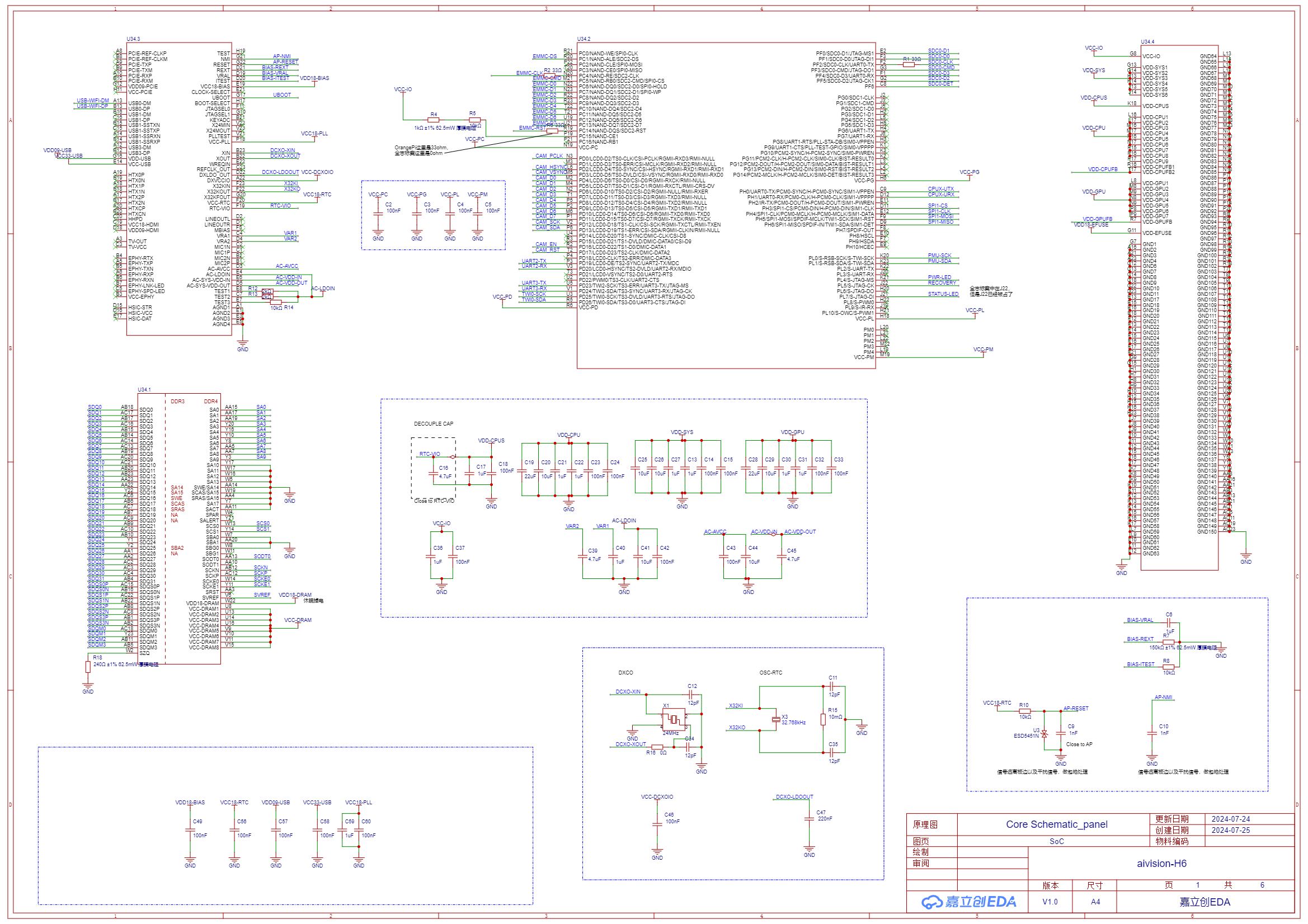
Attached is the partial schematic of the core board. The complete schematic documentation can be found in the related attachments section.
[1] Main Controller Chip Allwinner H6 SoC
[2] Memory Chip LPDDR3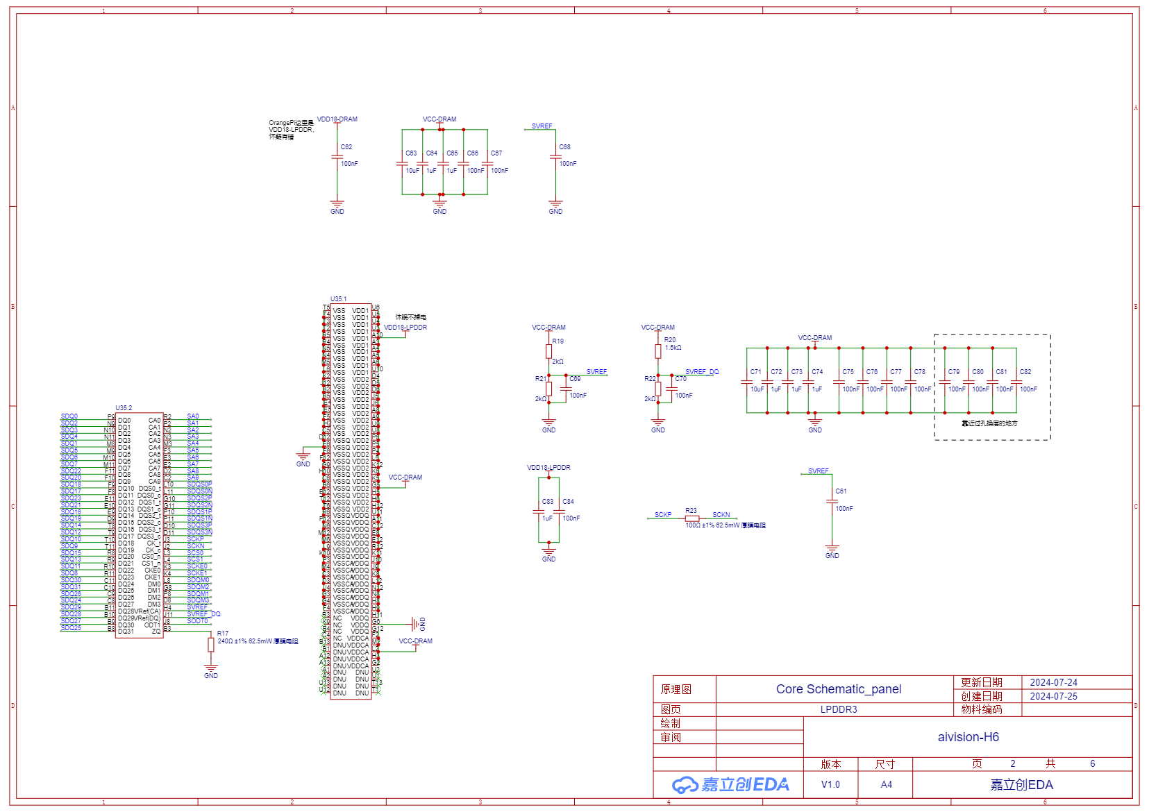
[3] Storage eMMC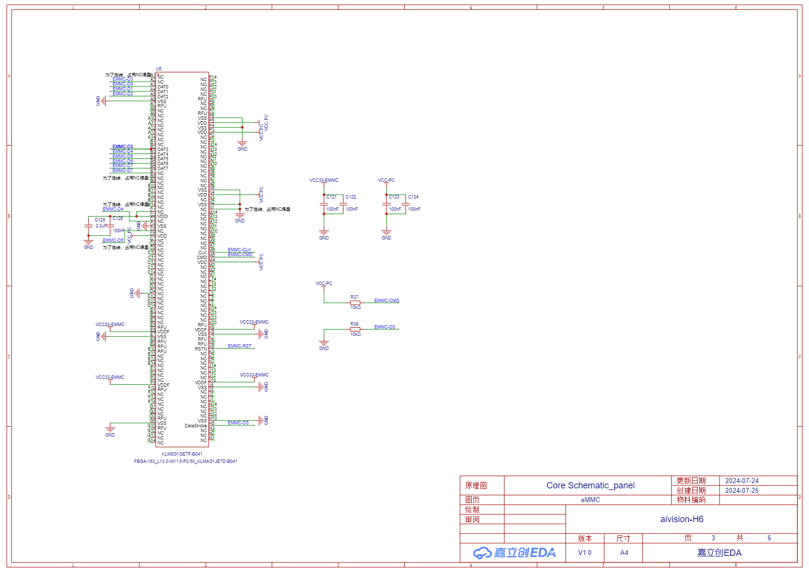
[4] Power Management Chip AXP805 and a DC-DC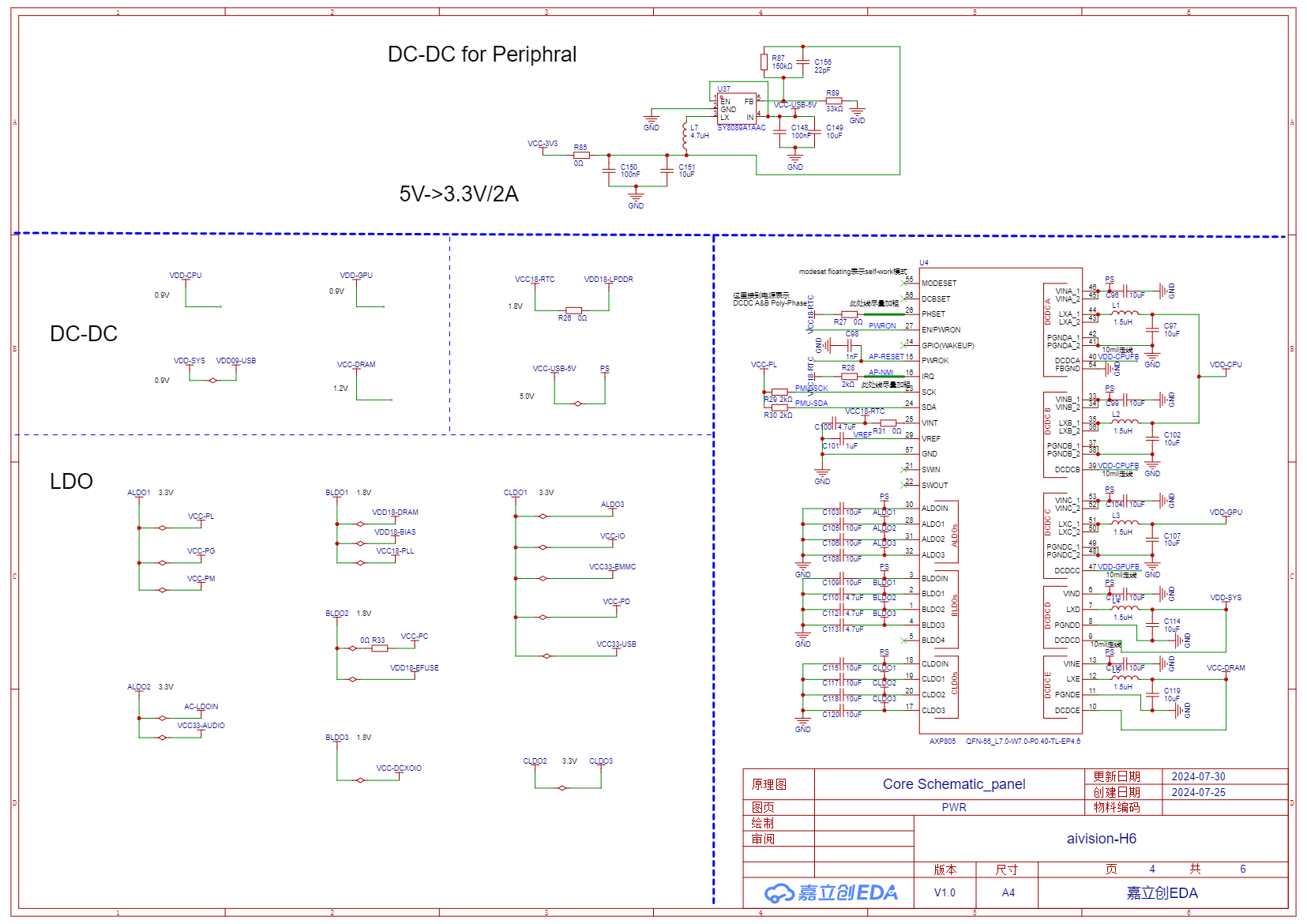
[5] Golden Finger Interface Definition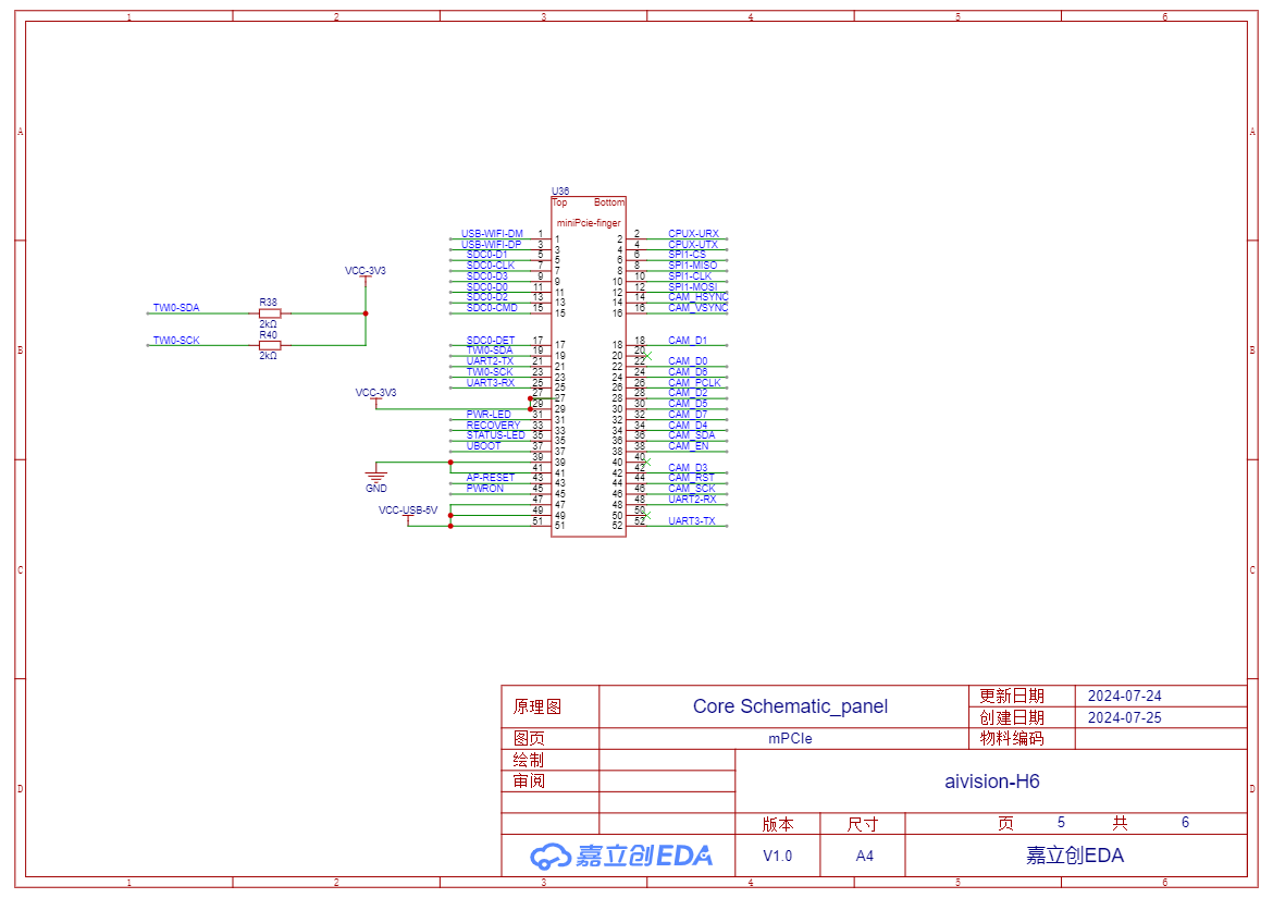
PCB Layout (Non-source files)
Top Layer of Core Board PCB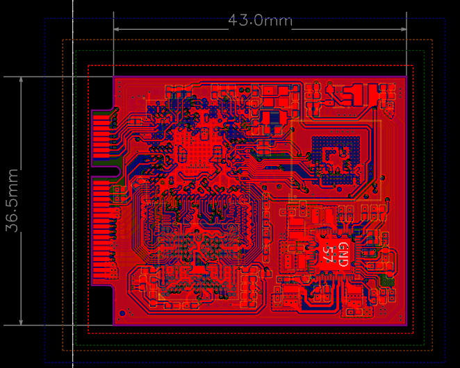
Peripheral Board PCB Top Layer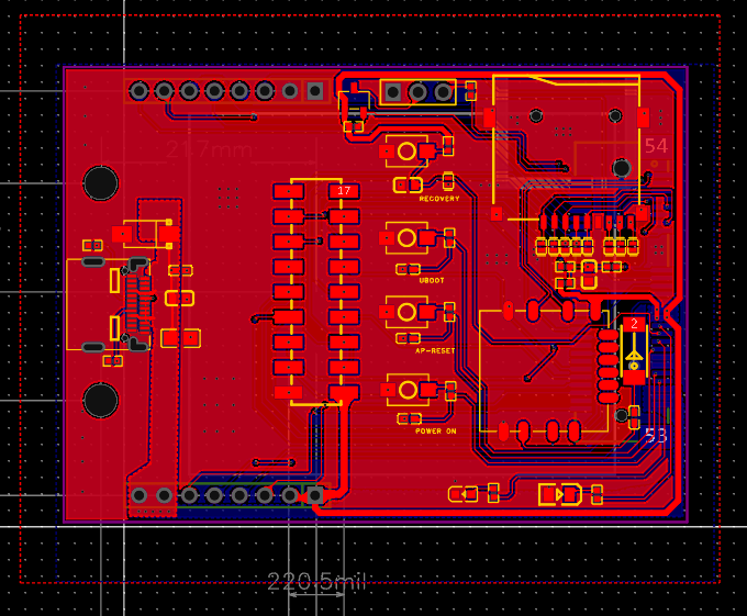
3D Rendering
Core board 3D rendering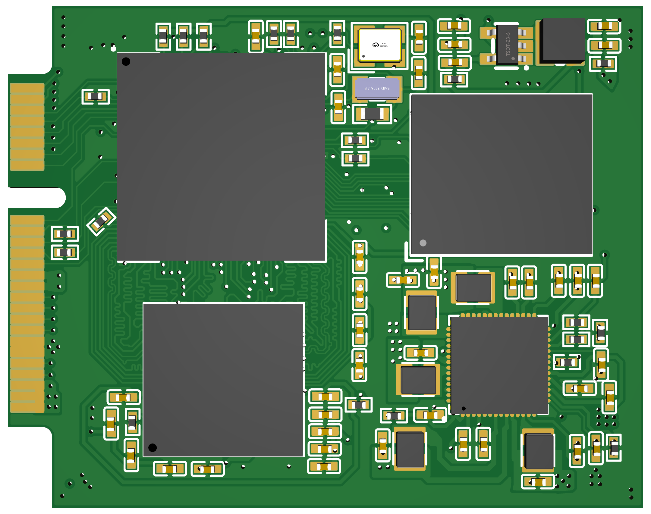
Peripheral Board 3D rendering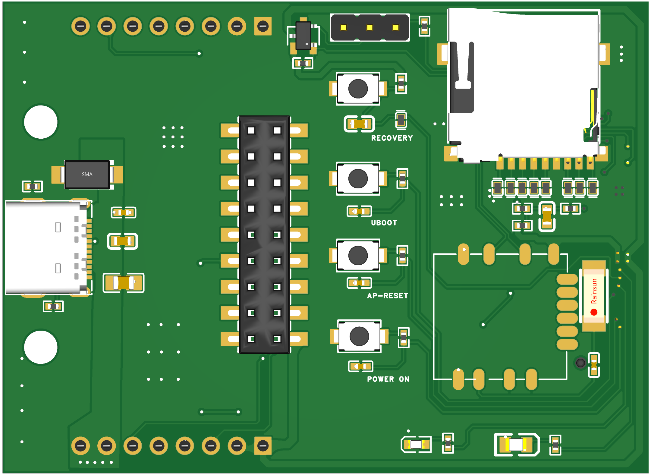
Circuit Debugging Instructions
- After receiving the board, write the Linux system image file (the image file can be found in attachments) to the TF card and insert it into the TF card slot.
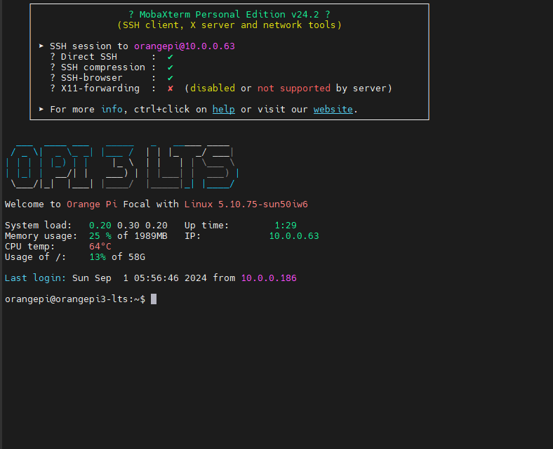
- Use a USB to TTL serial module. Connect one end of the serial module to the serial pin header interface on the peripheral board using three Dupont wires, and connect the other end (USB 2.0) to the PC. For Windows systems, use MobaXterm software, create a new serial session, and wait for the board to start.
- Press and hold the POWER ON button on the peripheral board until the red LED lights up. Release the button, and after a few seconds, the yellow LED will light up and the red LED will turn off, indicating successful board startup. At this time, the serial session should display the boot log output. Wait for the login prompt.
- Enter username "orangepi" (the system uses orangepi3-lts system) and password "orangepi" to enter the system command line interface.
- Use the command line interface under serial connection to set up the board's WiFi connection. After this, you can disconnect the serial connection and operate the board directly through an SSH wireless connection.
Physical Product Display
Core Board: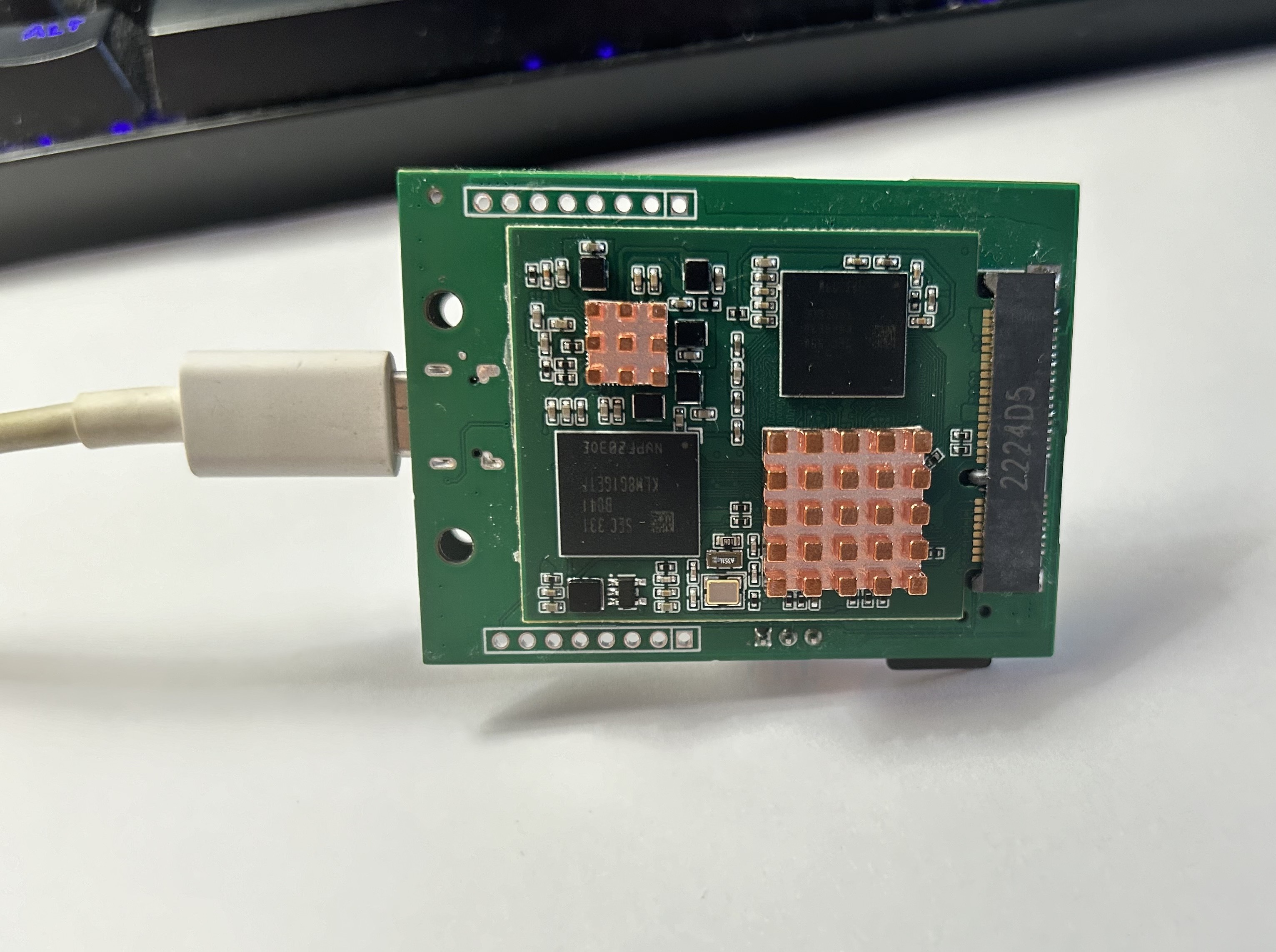
Peripheral Board (core board is attached via Golden finger interface at back):
Contact Us and Technical Support
- Join us in Slack.
- Links to detailed board documentation will be added later, including AI vision models and applications developed based on the board.
- Purchase links for the board will be added later.
[相关附件]
Acknowledgements
The development of this project received help from many people. Thanks to Orange Pi for their Linux image documentation, and LogicWorld for sharing their materials。
Discussions
Become a Hackaday.io Member
Create an account to leave a comment. Already have an account? Log In.