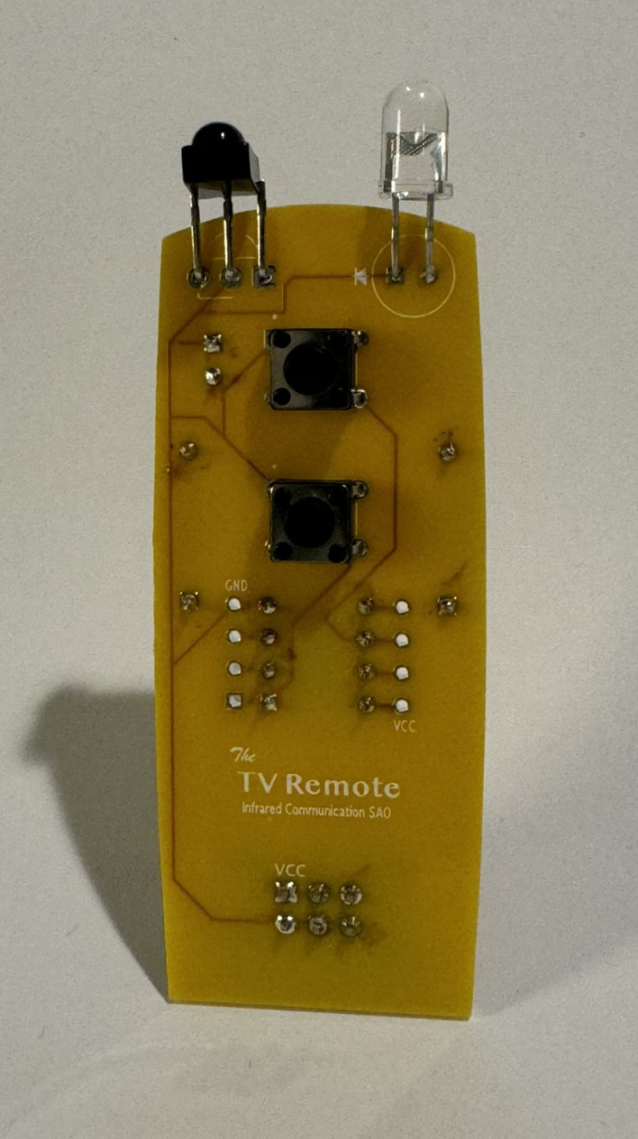
It's alive!
Hello everyone!
This update will be going through the validation process for our first prototype boards.
I have begun to call them Version 0 boards give the handful of issues that popped up.
Overall it looks amazing! For my first attempt at a PCB, I am quite please reguardless of the handful of issues.
Programming the ATTiny85 was simple enough. Unlike the version in the photo, I added the optional pin headers to the board I was using for validation like shown below.
Using the pins, programming and testing was extremely simple. I added a DIP socket to the first board as well just to add additional troubleshooting options if needed. This ended up not being needed.

Testing the hardware, the first issue found was the IR Led.
Running code to transmit seemed to do nothing. I verified this with my photo to see if I could spot the IR Led and saw nothing. It seemed odd but I had a feeling there might have been an issue with the polarity and simply flipped the IR LED. Surprisingly this fixed the issue and transmitting was no longer a problem.
Next bit of trouble I found was using the SAO header for Serial.
This was never in the design but actually using the SAO board, I realized having Serial for debugging would be very useful. I ended up using the SCL pin and ATtinySerialOut library.
The ATTiny85 requires software serial to get any serial support. SoftwareSerial was an option however, ATtinySerialOut was used due to the VERY limited space on the ATTiny85. Additionally, the ATTiny85 clock speed needs to be set to 8MHz instead of the default 1. That took me a little bit to realize of course.
I've decided to add an optional pin header for TX out to simplify things instead of having to wire through the SAO headers. That said either Serial or i2c can be used, not both.
Now the IR Receiver, I spent a good while troubleshoot this. In the end I spent hours not realize that the incorrect pin was being used to initialize the IR Receiver and since it was default to Pin2, the ATTiny85 would just hang.
The one issue I did find was for the solder bridge to avoid using a resister and capacitor. While troubleshooting and removing components to see if that was the issue, I discovered the solder bridge was way too small to use.
The reset button worked great. :)
I have yet to test the i2c functionality but we suspect that will require 10k resisters to work correctly. Also I still need to test the top button and the GPIO functionality.
Once that's done, we will order another batch of PCBs. This version I will be calling version 1 hopefully.
Oh and of course the code can be found on Github:
https://github.com/alecjprobst/IR-Transceiver-SAO
The repository is currently quite barren since we are just doing validation of the PCB design. However, full instructions and guides along with a few sample programs will be found there soon.
PCB Updates needed:
- Add a TX pin header option.
- Flip IR Transmitter polarity on silkscreen.
- Increase size of solder bridge.
- Resisters for i2c.
- GPIO Validation.
- A couple of random silkscreen text changes.
Discussions
Become a Hackaday.io Member
Create an account to leave a comment. Already have an account? Log In.