SignalRGB Keyboard Wall Blog
Written by Robbie Pollard
Built by Chris Miller https://chrismillerstuff.com
1. Introductions
This blog will document how Chris Miller in collaboration with SignalRGB recently built a keyboard display wall. This will be more of a guide for you to base your own projects off of and may be used as inspiration and as well as give insight to some problems you may encounter in your own designs. We will give details on products used and will provide links at the end of the blog for some of the specialty materials used.
2. Preparations
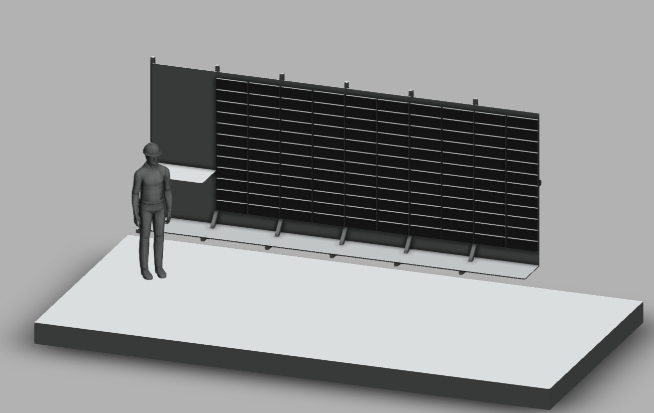
The keyboard wall will require some planning before you start the project. Planning is mostly on what keyboard you plan to use and what size you want to make the wall based on the size of the keyboard. This project is used at tradeshows and also includes a built in kiosk to control the wall but you may wish to forgo this addition. We started with a 3D render in Fusion 360 to plan out the dimensions of the wall and pay out how we want the wall to look like. We broke the wall into 6 sections with 5 sections set aside for keyboards and a single section set aside for the kiosk. One major thing we planned for is the wall is designed to be shortened and lengthened depending on the size of our booth at different tradeshows.
3. Materials Used
This section will be broken into smaller subsections. We always recommend buying extra beforehand in case you lose some bolts or damage them.
- We use 2020s extrusion for the frame. 36” for legs and 84” for vertical. https://8020.net/2020-s.html
- We use the https://8020.net/2567.html for the 45 degree supports.
- We use 1/2” plywood for all panels.
- We use the Element V2 for the keyboards but have since sold out, can be done with any ARGB keyboard with per key LED control but will need dimensions changed.
- And we 3D printed all the brackets for the keyboards. Which will need to be changed on a per keyboard model basis.
- STL files for the keyboard brackets. Also has autocad files for the base panels. https://drive.google.com/drive/folders/1yjGiT4GoSct8ABbWDVRsOW4wFXy0p810?usp=sharing
4. Keyboard Preparations
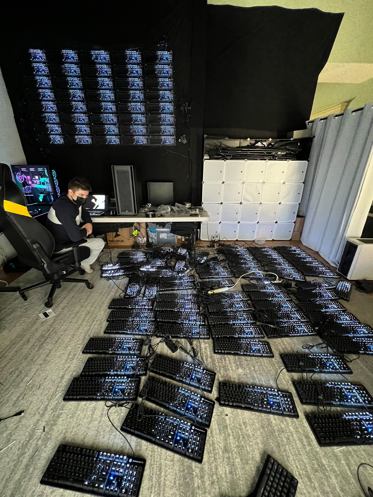
We used the WhirlwindFX element V2 keyboard for this project. Since the wall is made of devices used to interact with computers on a core level we needed to disable the keyboards from working to ensure the display cant be tampered with. We did this by flashing custom firmware to the keyboards that disabled their keys. We found people love coming up to the wall and just pressing random keys as they are mechanical keyboards and this will save you from a lot of heartache later on.
5. Assembly Instructions
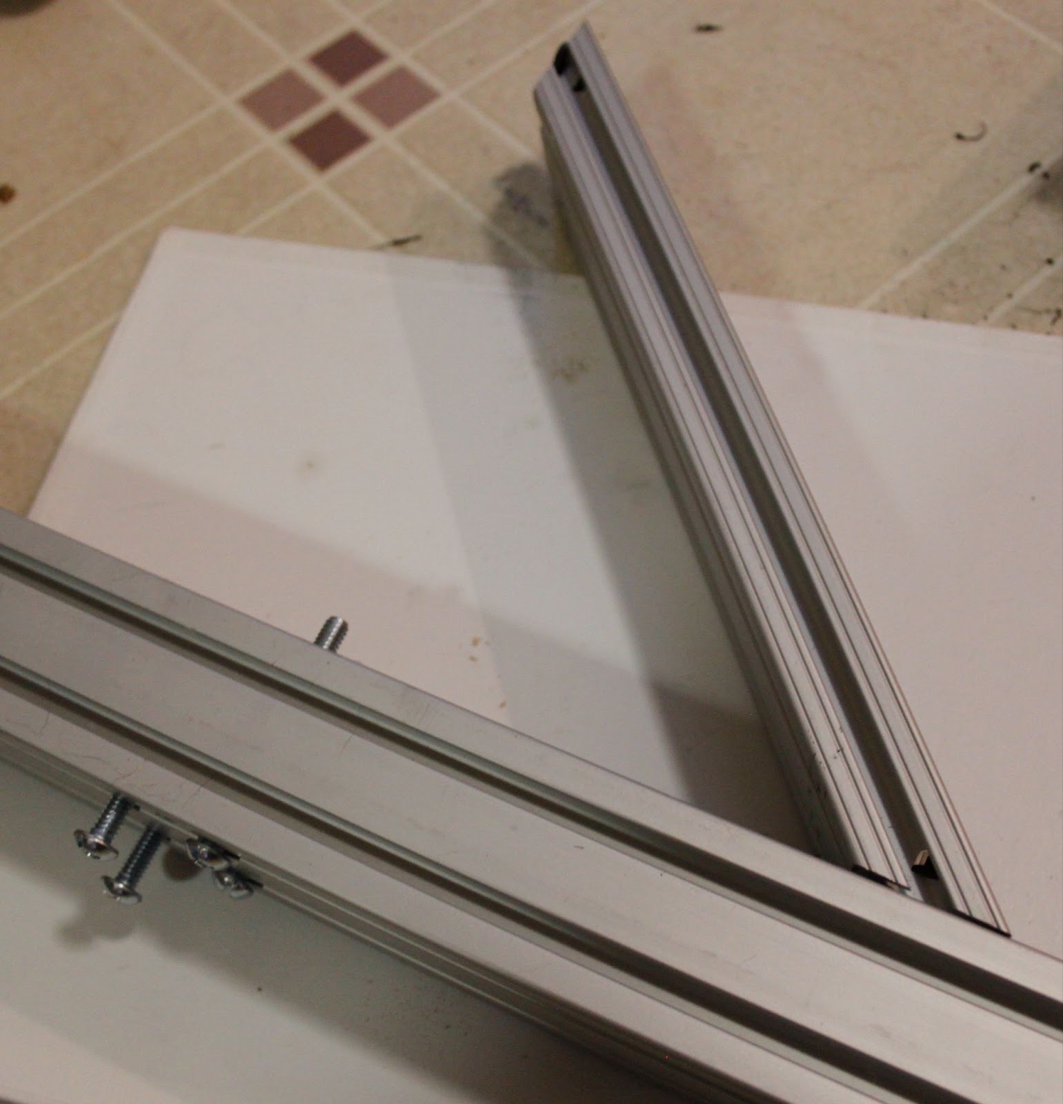
5.1 Frame assembly
A. Arrange 36” leg and 90” upright on floor, aligning 4 holes in leg with thread
tapped end of the upright.
B. Slide the tee-nuts on the 12” long, 45 degree extrusion bracket into slots on the top surface of the leg and the front surface of the upright. Do not tighten screws yet.
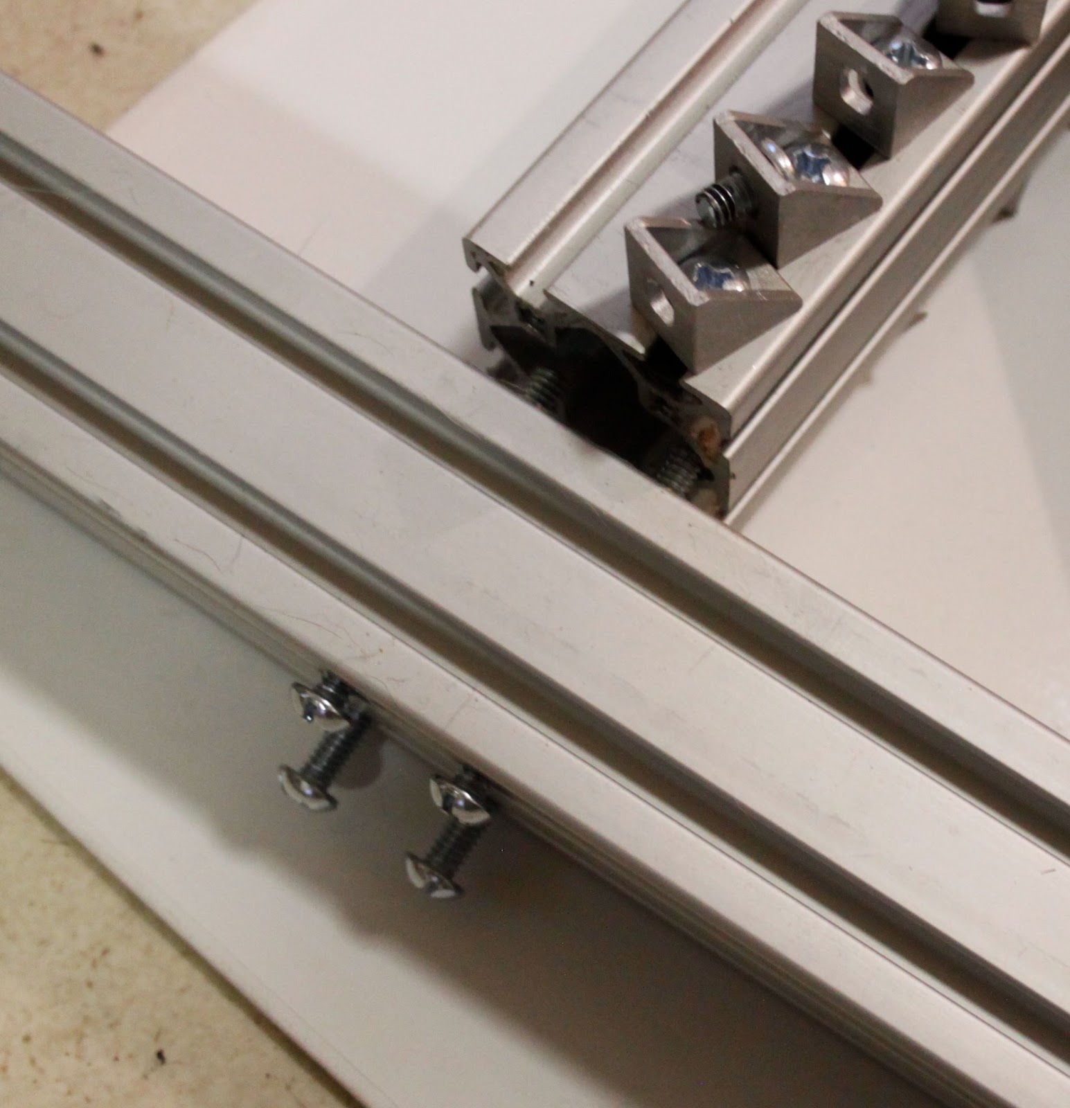
C. Insert 4x 2-½” x ¼-20 machine screws through the four holes through the leg and into the upright. Tighten these screws now. Extrusions should pull into roughly square.
D. Tighten the four black screws on the 12” long 45 degree extrusion bracket.
Repeat for as many panels needed.
5.2 Panel Assembly
- Identify front and back sides. 4 metal threaded inserts are visible on the front side. When viewing the front side, the ¾” keyboard cable holes are on the right side.
- Insert 1-¼” x ¼-20 screws into the 16 unthreaded keyboard mounting holes from the back side.
- Install the bottom row of brackets. Bottom panel can use a full bracket, middle and upper panels need a top half bracket
- Slide two keyboards into the bottom brackets, routing cables through holes at the right end.
- Place two full brackets on the screws and tighten. Cable should be hidden...
 inboxsahil.sahajpal
 Cory Whitesell
 lambtor