 Ricardo Daniel de Paula
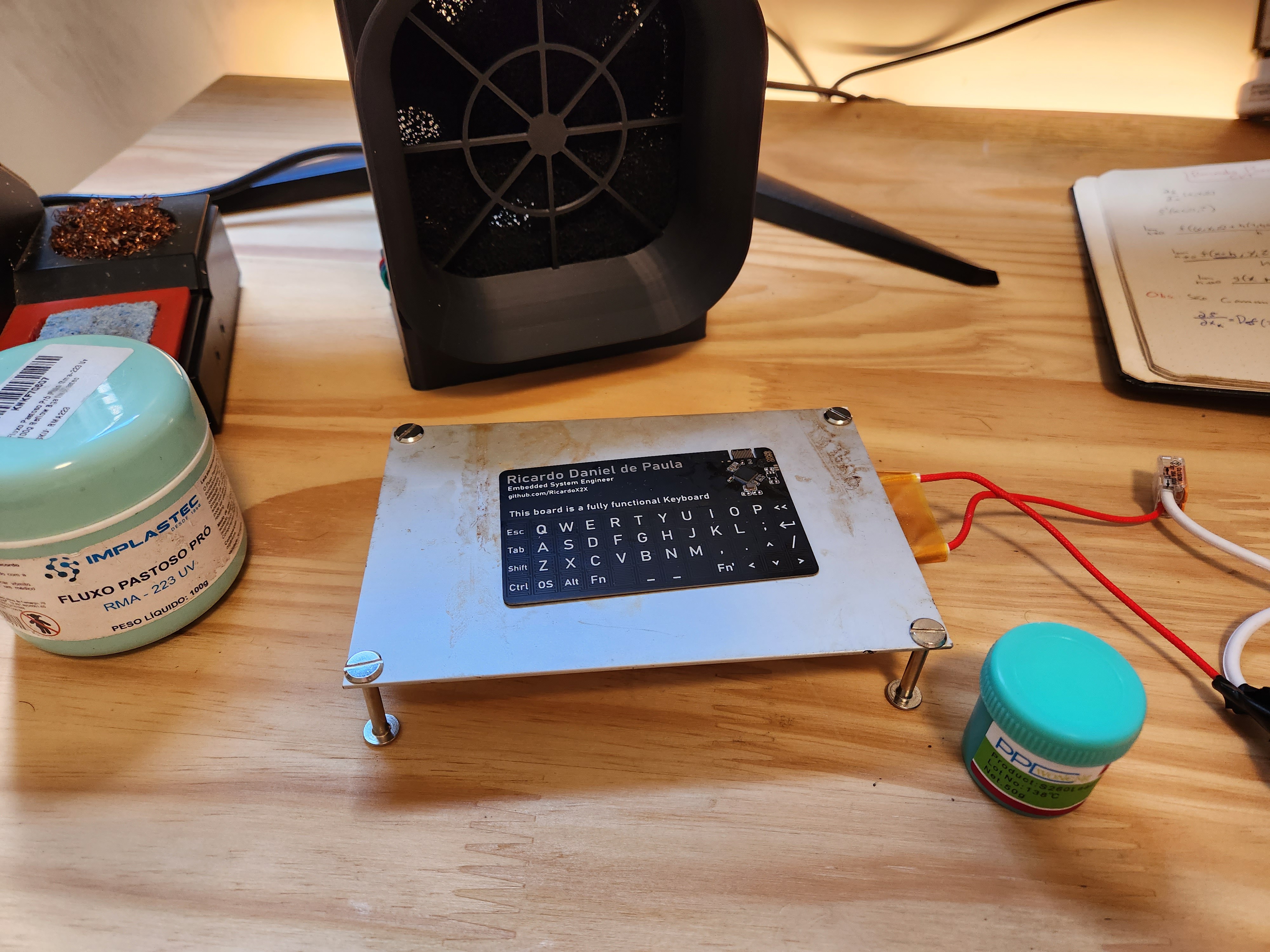
The project has received incredible feedback since the last post, especially after being featured on Hackaday (check it out here). Many people have asked for updates through various channels, so here I am to share the latest progress, challenges, and lessons learned!
Special Thanks to PCBWay
First and foremost, a huge thanks to PCBWay, who sponsored the first PCBs with the correct color, thickness, and finish. A special shoutout to Liam for making this support possible! Without them, this project wouldn't have progressed so smoothly.

Soldering Process
The components were soldered using a improvised hot plate and low-melting-point solder paste (138°C). Due to the small components and compact design, a lot of patience was required to ensure proper alignment and avoid shorts.
PCB Design Errors and Improvements
No project is without challenges, and this one was no exception. Here are some areas for improvement in future revisions:
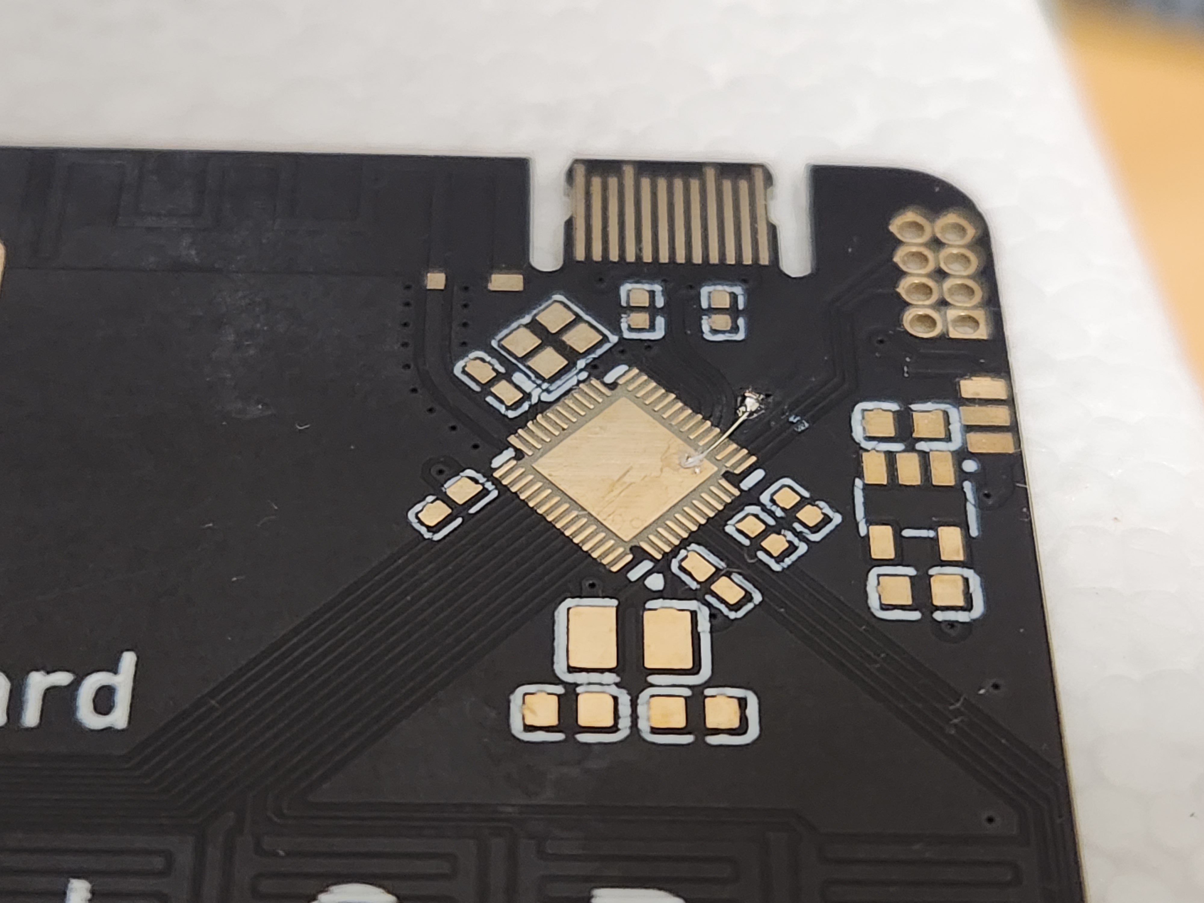
- Microcontroller GND connection error:
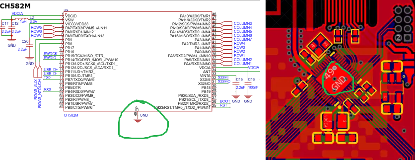
The main GND connection ended up being disconnected on the manufactured PCB. This happened because the EP (Exposed Pad) of the microcontroller should have been connected to the GND plane underneath the chip, but this was overlooked during routing, so i have to do a quick fix:
The error has already been corrected in the schematic and PCB in the EasyEDA project:
- Lack of indicator LEDs:
Initially, I omitted LEDs to reduce costs. However, I later realized that having a power LED and another to indicate Caps Lock or other functions would have been very useful. In the end, the cost-saving decision was negligible and not worth it.
- PCB thickness and USB-C fit:
I opted for a 0.6mm thickness since the USB-C connector documentation specified 0.7mm. Unfortunately, this 0.1mm difference resulted in a slightly loose connection. Since PCBWay doesn’t offer 0.7mm PCBs, 0.8mm might have been a better choice for a more secure fit.
Entering the Firmware Realm
Now it's time to dive into firmware development! This microcontroller does not support the Arduino IDE, which might have made development faster and more convenient. Because of this, I'm using WCH's development environment, MounRiver Studio.
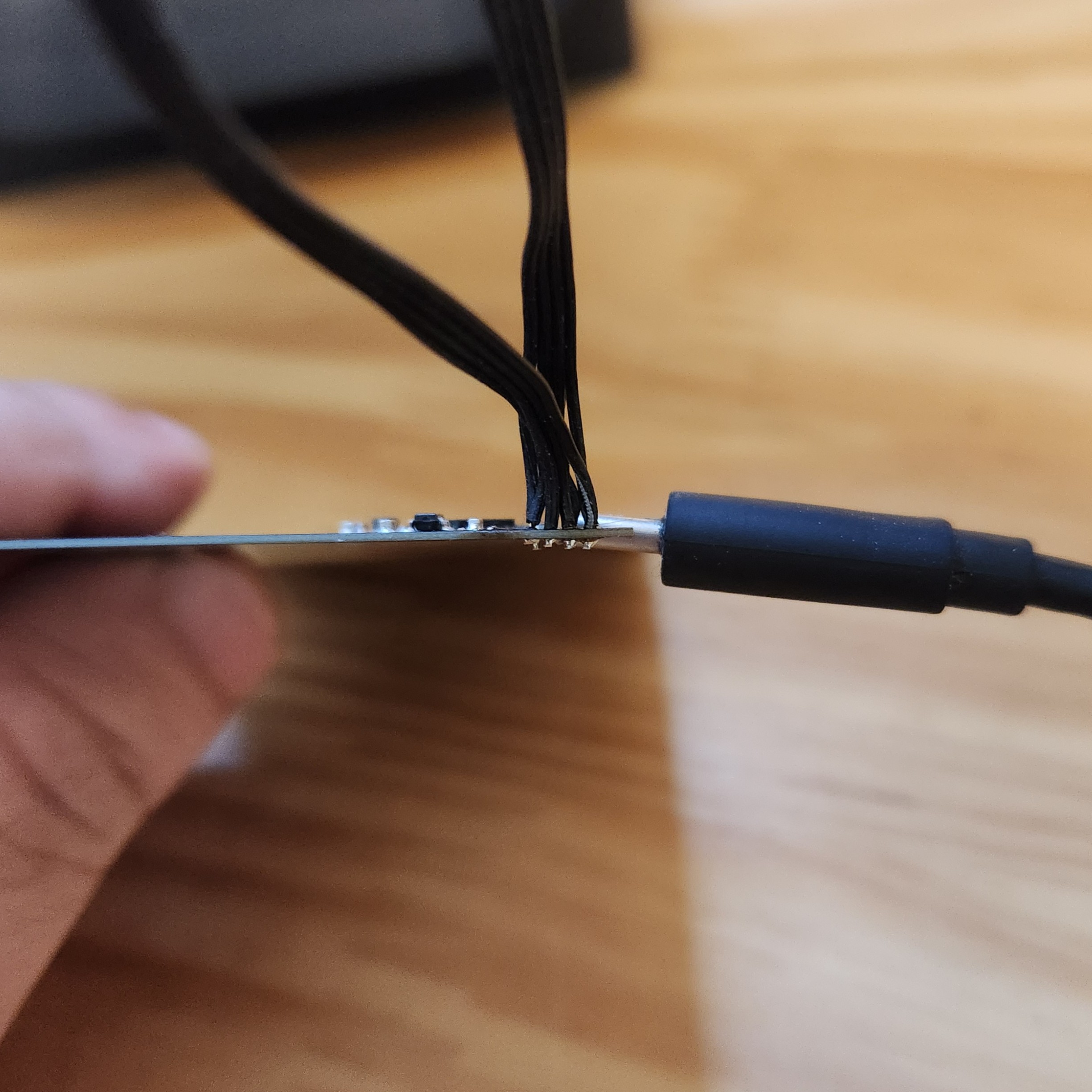
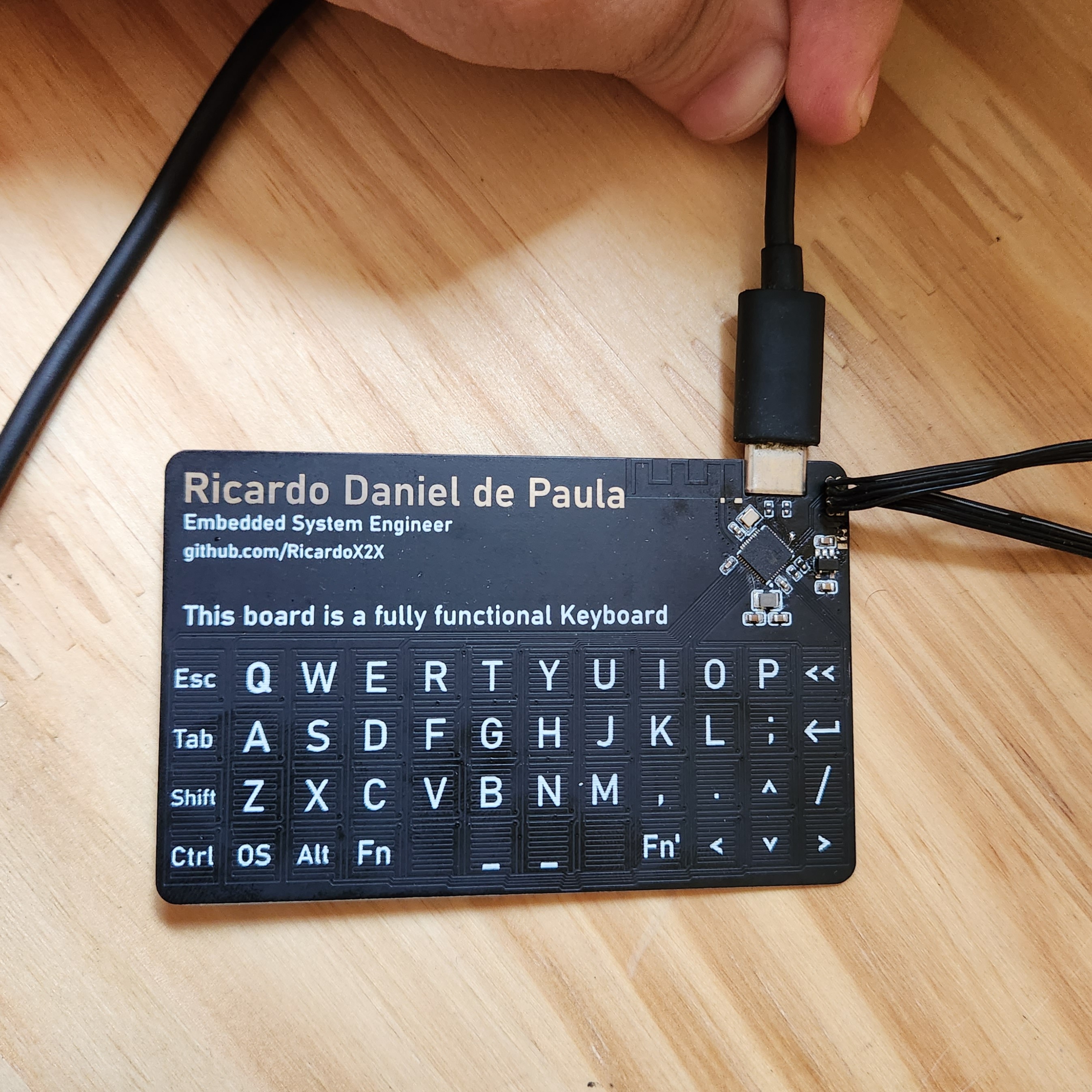
To facilitate debugging in this first version, I also soldered some wires to the programming connectors. This will make it easier to test and refine the firmware as I go. I’m happy to report that I’ve already managed to execute code on the microcontroller
But i will be making a dedicated post specifically about the firmware development process.
Thank you all for your support and feedback! Stay tuned for more updates soon! 🚀
Discussions
Become a Hackaday.io Member
Create an account to leave a comment. Already have an account? Log In.