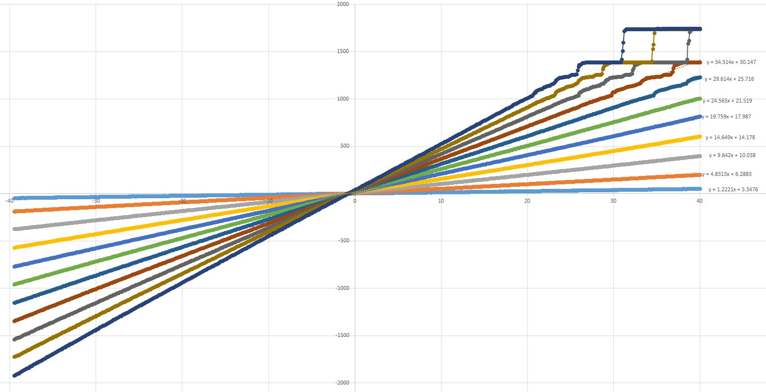
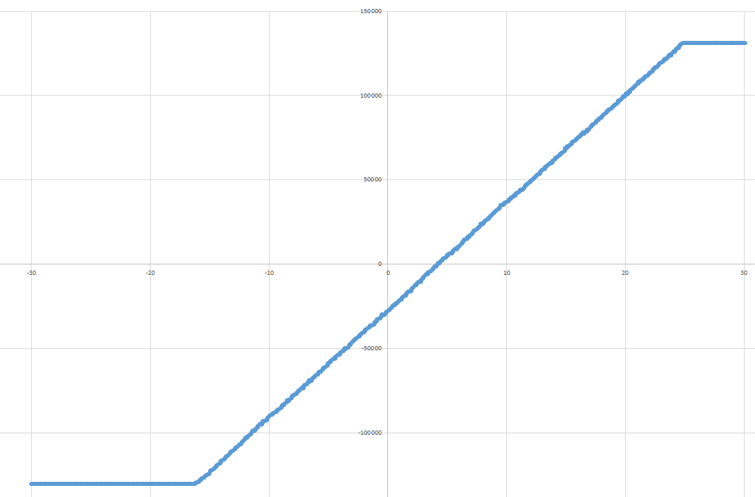
The goal was to convert signal 0 - 5V centered around 2.5V. It was evaluation of better ADC for precise measurement instrument. AD7691 18-bit SAR ADC was chosen. Nice differential input, 250ksps, great linearity, low errors. I made gain calibrations (real output voltage vs adc measured voltage) for the instrument and the results were shocking. Upper 25% of range was bullshit ( stuck codes, missing codes, even codes that corresponds to 19bit ADC :) ) and measurement was not to be trusted. Hmm I have probably damaged internal circuitry by accidentally increasing VDD to 8V for short period of time. But changing ADC didnt help. Problem was elsewhere.

( http://electronics.stackexchange.com/questions/114825/stuck-codes-in-samples-from-adc )
Visiting datasheet again I have found one funky value I wasnt checking during the design because I have expected common mode range to be 0 to VREF, but LOL it is VREF/2+-0.1V. This means that I cannot feed VREF/2 signal to negative ADC input, but negative copy of my signal centered around VREF/2 instead.
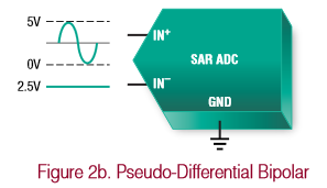
Long story short AD7691 is true(fully) differential unipolar ADC and my signal was for pseudo-differential bipolar ADC or true differential with wide common mode ADC :-)
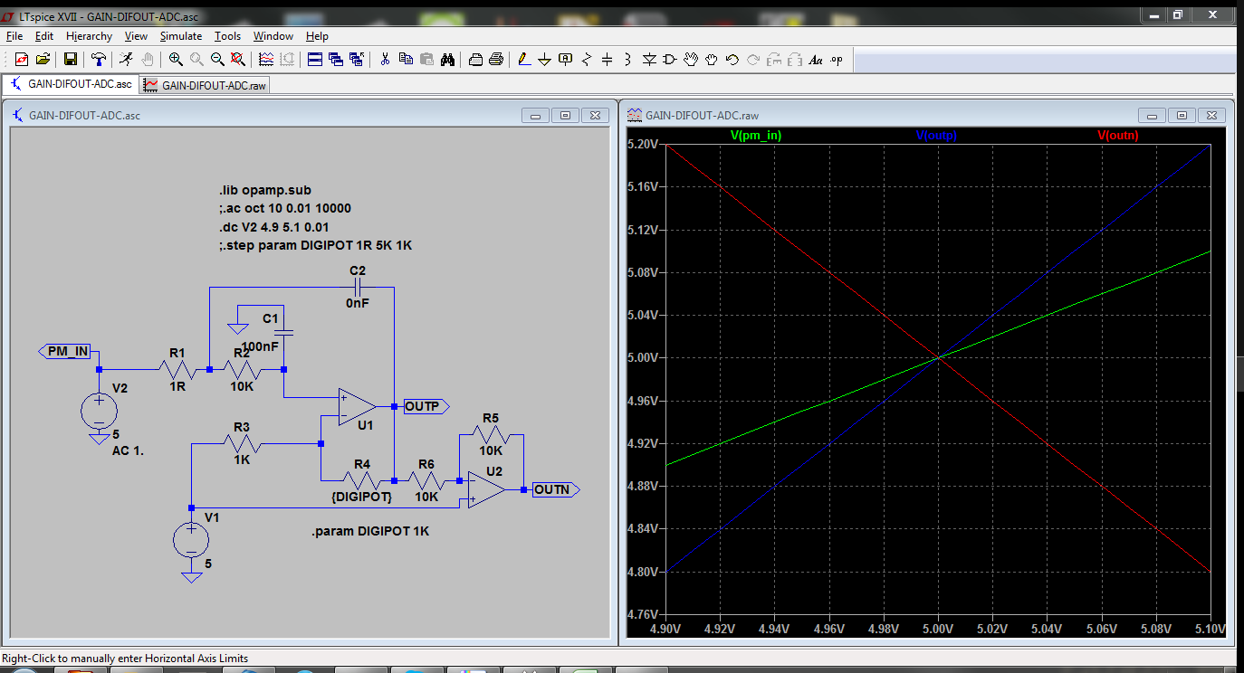
Simulation says it works, common mode is in range.
Solved :)
 kevarek


Discussions
Become a Hackaday.io Member
Create an account to leave a comment. Already have an account? Log In.
You got ADC common mode and also solution correctly. BTW there is a hint about this behavior on first page of datasheet:
http://www.analog.com/media/en/technical-documentation/data-sheets/AD7691.pdf
On the CNV rising edge, it samples the voltage difference between the IN+ and IN− pins. The voltages on these pins swing in opposite phase s between 0 V and REF.
True differential analog input range: ±VREF 0V to VREF with VREF up to VDD on both inputs
I think the whole ADC input terminology is confusing for a firsttimer who has experience with differential measurement probes etc :) But when you know the terminology it is quite straightforward.
0.005R current measurements been there done that, not again, but got it working for 20Amps range :)
And using resistor dividers in high speed communication - fortunately I got some nice I2C experience about slew rate, bus capacitance etc before I got burned :)
Anyway it seems, as I have expected, that all the electrical guys do the same mistakes essentially. THERE SHOULD BE A BOOK WHAT NOT TO DO :)
Are you sure? yes | no
seems you've got a good start on that book :)
Are you sure? yes | no
common-mode voltage bites me in the butt recurringly when I work on analog circuitry.
So if I grasp your experience, here, correctly, you tied your 0-5V input signal to one side of the ADC's differential-input, then tied the other ADC input to 2.5V, to measure the difference between your input signal and 2.5V, with a *differen*tial ADC. Makes complete sense. But what was happening, due to the ADC's input-structure, was the common-mode voltage varied dramatically with your input-voltage. E.G. with an input of 0V, your common-mode voltage would be 1.25V, and with a 5V input, your common-mode voltage would be 3.75V. Wouldn't think to look for that, from a brief look at the ADC's description! It basically means that the ADC expects both its input-signals to vary equally (and oppositely) around 2.5V! Kinda defeats the idea of a difference-measurement. :/
(I ran into similar with trying to create an LVDS-driver circuit, if the input voltage is +-100mV, then why not tie one input to 2.5V and use a 1/25 voltage-divider between that and an input-voltage switching between 0V and 5V? No go. And a slew of other, more-analog, circuits where common-mode wasn't a consideration until it was all soldered-up and failed: FYI it's really difficult to measure current by feeding the voltage across a 0.01ohm resistor--in series with a 24V supply-voltage--into an op-amp! And only slightly less-difficult if you put that resistor on the ground-side instead. If I had a "lifetime fails" project, forgetting about common-mode voltage would show up on it *numerous* times.)
If you've got a single-ended input from 0-5V, but want its measurement to be centered around 2.5V, maybe it would be easier to just use a single-ended ADC and shift the (digital) output-value by half the range, rather than introduce measurement-error via external circuitry...?
Great solution, though, if I understand it correctly, for working with your differential-ADC... to essentially invert your input signal around 2.5V, and feed both into the ADC, as long as the common-mode voltages of the op-amps are kept in check, as well ;)
Are you sure? yes | no