Close
0%
0%

Tokamak in Your Home: A Xenon Plasma Toroid

We have built a beautiful purple plasma ring and everything about it is open source.

Similar projects worth following
We have built a beautiful purple Plasma Toroid, and everything about it is open source. All the parts can be purchased cheaply, and we believe this is the lowest-cost way to build your own Plasma Toroid in the world.

## Disclaimer
Before using this document to make a plasma toroid, please carefully read the following important safety warnings and disclaimers. Using this document means that you fully understand and agree to the following terms:
- Dangers of plasma toroids: The glass bottle will generate high temperatures when the plasma toroid is running, and there is a risk of low-temperature burns. It is never recommended to directly touch the running glass bottle with your hands to avoid burns.
- Magnetic field warning: The plasma toroid will generate a strong magnetic field during operation. For people wearing pacemakers and other medical devices, strong magnetic fields may affect the normal operation of the devices. We recommend that these users stay away from working plasma toroids to avoid potential health risks.
- High voltage risk: The drive circuit of the plasma toroid will generate high voltage during operation. High voltage poses a danger of electric shock or burns. Please do not touch any components, including the primary coil, while the circuit is working to avoid electric shock or burns.
- Component temperature: Please note that some components of the circuit may become very hot during operation, which may cause burns. When the device is running, especially after running for a long time, do not touch these components.
- Electromagnetic interference: The plasma toroid will emit electromagnetic waves around 10MHz when running. This band will not harm the human body, but it may interfere with some electronic devices operating in this band, such as touchpads and card readers. Please keep these devices away from the working drive circuit.

Using this document means that you understand and agree to bear the risks of use. The author is not responsible for any direct or indirect damages caused by not following the safety guidelines.

DIY with caution, safety first!

## Analysis of the Working Principle of Plasma Toroids

  - Glow discharge phenomenon: Under certain conditions, the gas will undergo glow discharge under the action of a strong electric field. In this process, the electrons of the gas molecules are stimulated and jump to higher energy level orbits. Since these electrons are unstable in the high-energy state, they will spontaneously fall back to the original low-energy orbit while releasing photons corresponding to the energy difference according to the law of conservation of energy. This phenomenon is called glow discharge and is applied to devices such as neon lights. The luminescence process of plasma toroids is similar to this.

  - Properties of plasma: In addition to the common solid, liquid, and gas states, plasma is another state of matter that exists in the universe, and flames are an example that contains plasma. When the gas is affected by high temperature, collisions between molecules will cause the outer electrons to escape their orbits, forming a plasma composed of charged particles. This charged ion mixture has electrical conductivity.
  - Generation of toroidal electromagnetic field: By passing a high-frequency alternating current through a toroidal coil, it can be derived from Maxwell's equations that the electric field distribution around it is toroidal. We use a self-excited Class E oscillator circuit to generate an alternating current with a frequency of about 10MHz.

  - Generation process of plasma toroid: In a spherical glass bottle filled with low-pressure xenon gas, the xenon gas is ionized under the action of a strong electric field to form a plasma. These conductive xenon gas plasmas form a stable toroidal structure under the influence of an external toroidal electric field. In the plasma, collisions of charged particles produce glow discharge, which emits a pale purple light, making the plasma toroid visible.

**When using and demonstrating the plasma toroid, please ensure that you understand its working principle and corresponding safety measures to ensure the safety of users.**

View project log

  • 1
    Preparation of Materials

    Materials

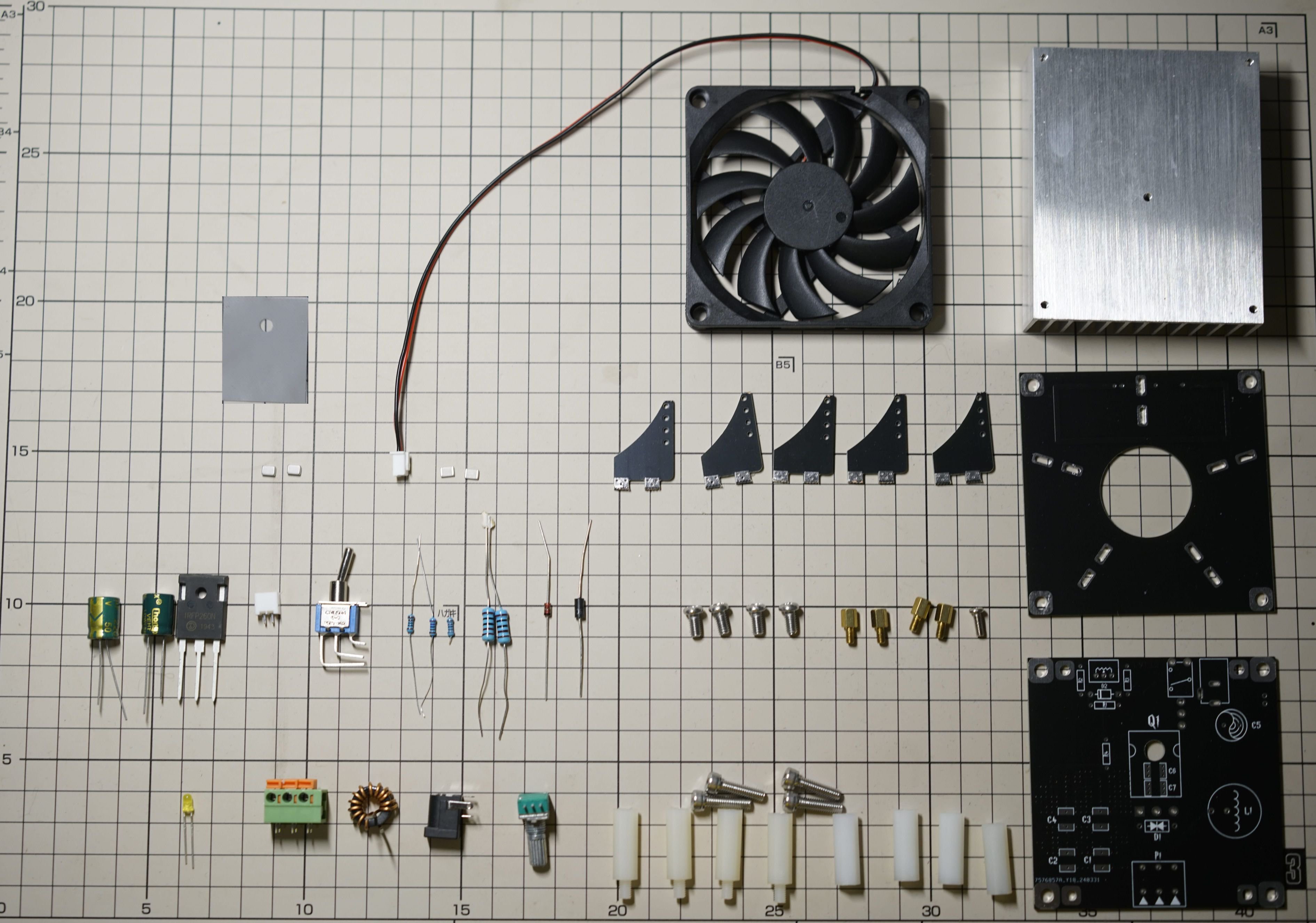
    - 82mm glass bottle filled with xenon gas (available in Aliexpress store **Diagon Alley Magic Shop**,You can find this store by searching for 'plasma toroid circuit DIY kit'. larger glass balls cannot be installed in the bracket of this project)
    - 1.2mm enameled wire - for winding coils
    - Black ring inductor 10uH  
    - Circuit board PCB (can be made using the files in the hardware folder)
    - Coil support, including base plate and five support pieces
    - Heatsink and fan
    - MOSFET IRFP260N
    - MOSFET heatsink silicone pad
    - Potentiometer 1k  
    - Resistor 1k * 3
    - Resistor 1.8k, 3k
    - SMD capacitor 100pf * 4
    - SMD capacitor 4.7nF * 2  
    - TVS 15V P6KE15CA
    - Voltage regulator diode 9.1V
    - Input filter capacitor Electrolytic capacitor 63V 220uf
    - Toggle switch
    - Green terminal block - for connecting coil
    - White fan socket
    - DC power interface - Light emitting diode
    - Screws and nylon columns
    - Piezoelectric ceramic removed from a lighter (used for initial ignition; this item is prohibited in air transport, so you may need to prepare it yourself, but the circuit can still be made without it)
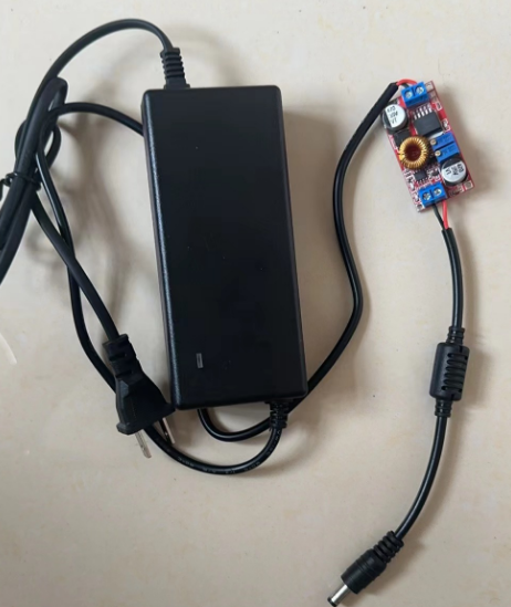
    - XL4015 current limiting module (this module is not required if you have an adjustable power supply)
    - 24V power adapter (4A or above, or you can use an adjustable power supply)

    Tools

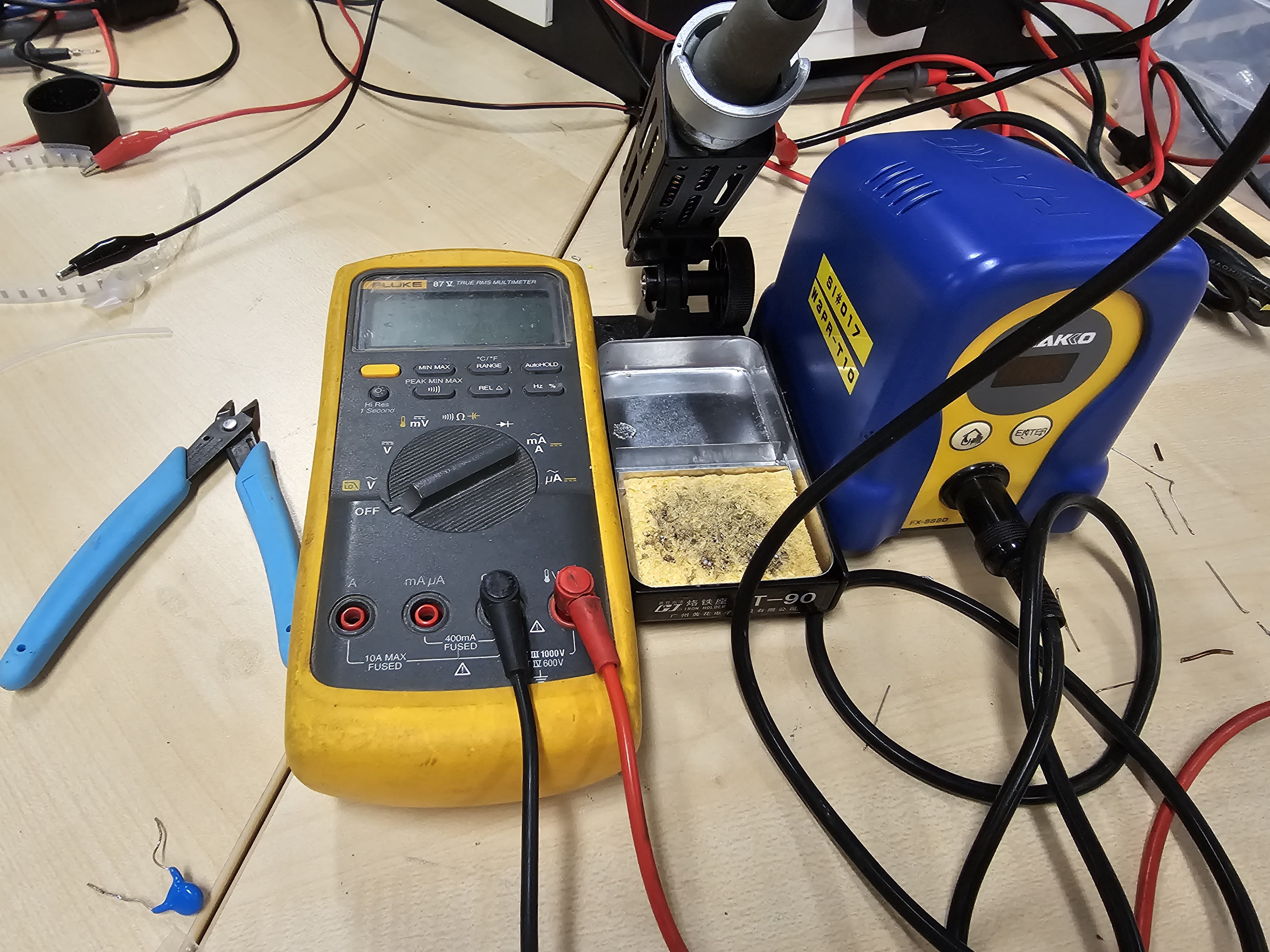
    - Multimeter
    - Soldering iron
    - Solder wire
    - Utility knife
    - Diagonal pliers
    - Hex screwdriver set - Tweezers (for soldering SMD capacitors)

  • 2
    Prepare the bracket and coil

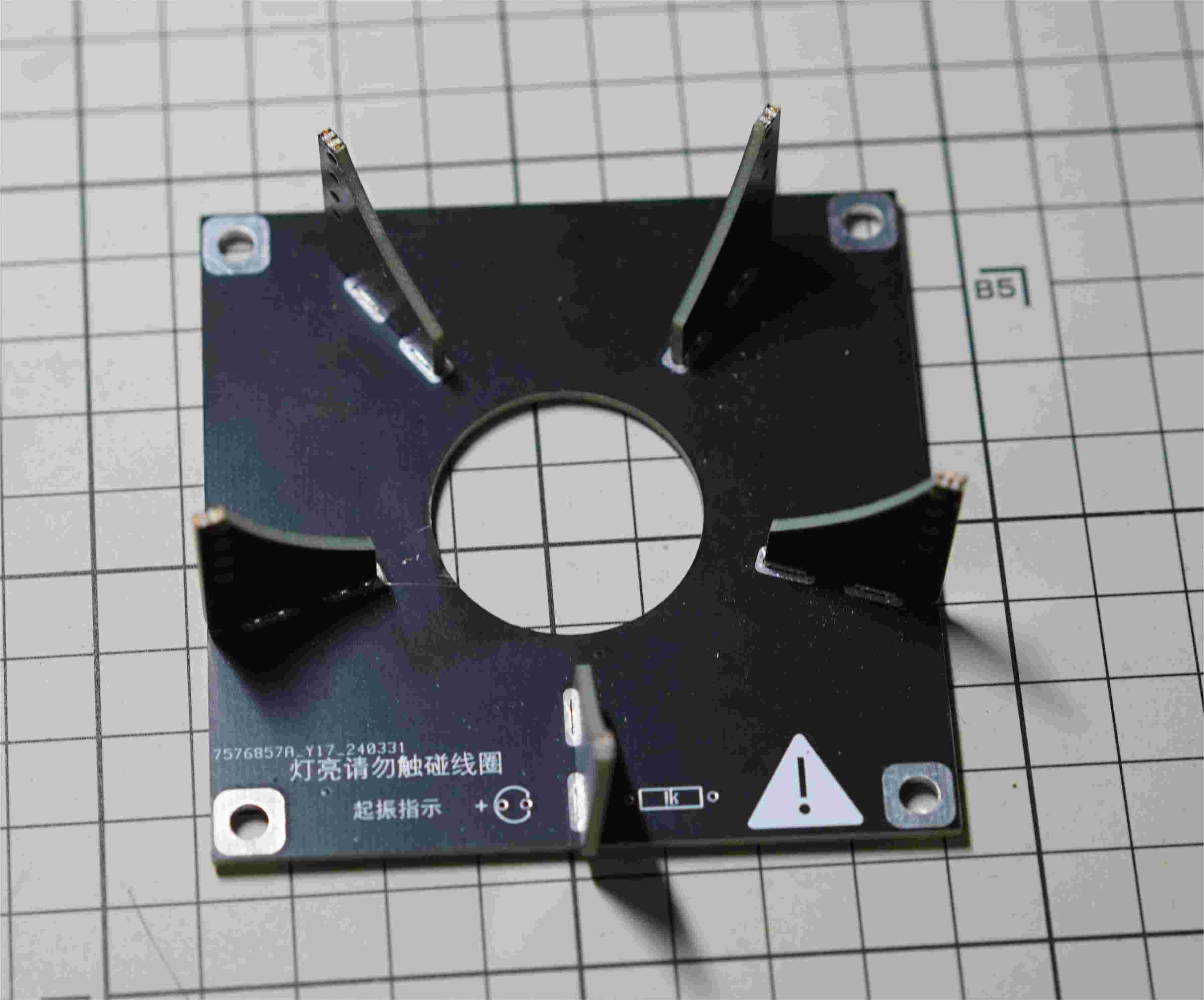
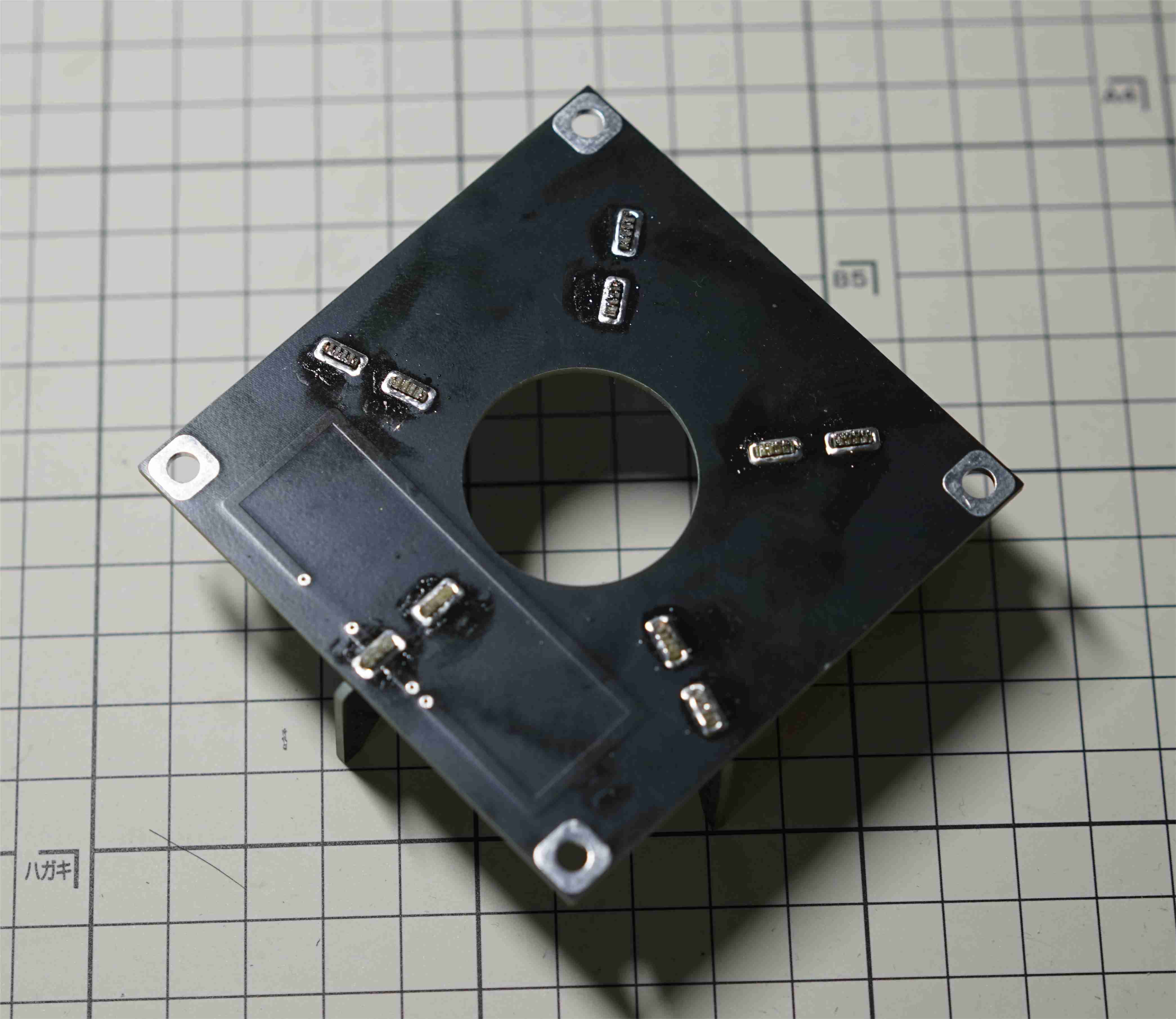
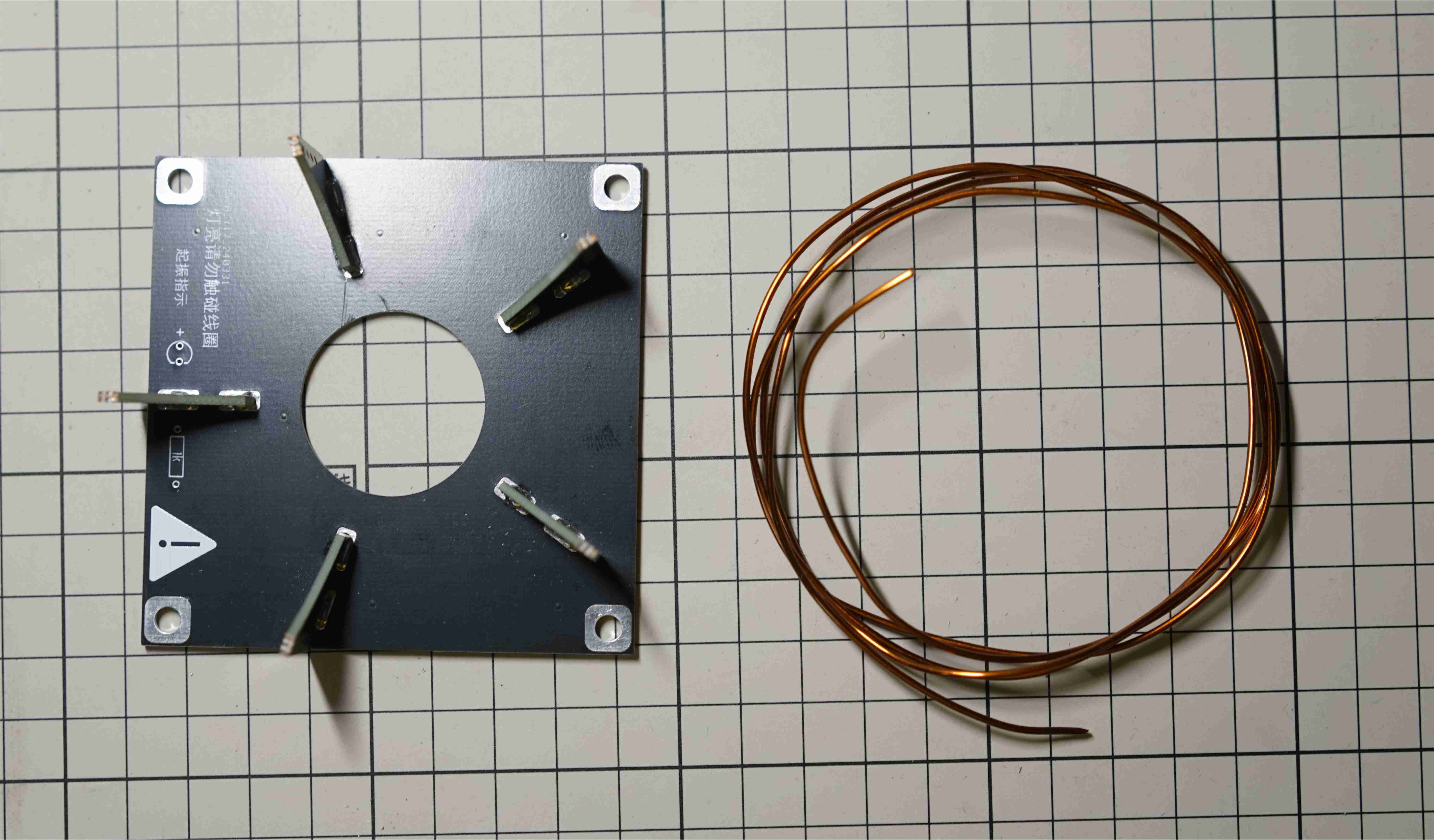
    - Prepare the five coil brackets, insert them into the base, heat up the soldering iron, and solder them in place with solder. Try to ensure that the brackets are perpendicular to the base plate. (The five coil bracket pieces need some force to fit in)

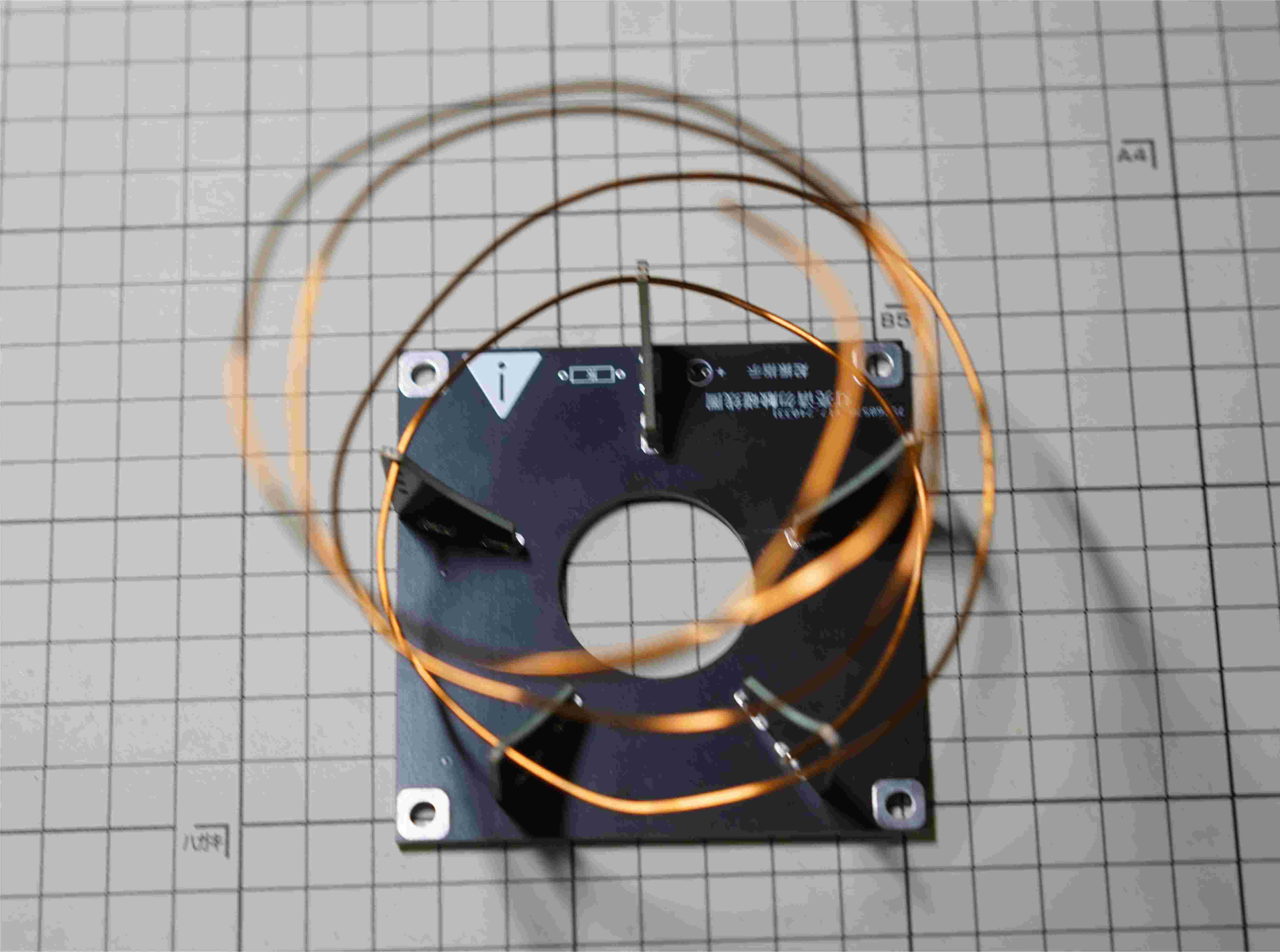
    - Bend the enameled wire according to the diameter of the coil frame, do not straighten the enameled wire, keeping the enameled wire bent helps with threading, once straightened it cannot be threaded.

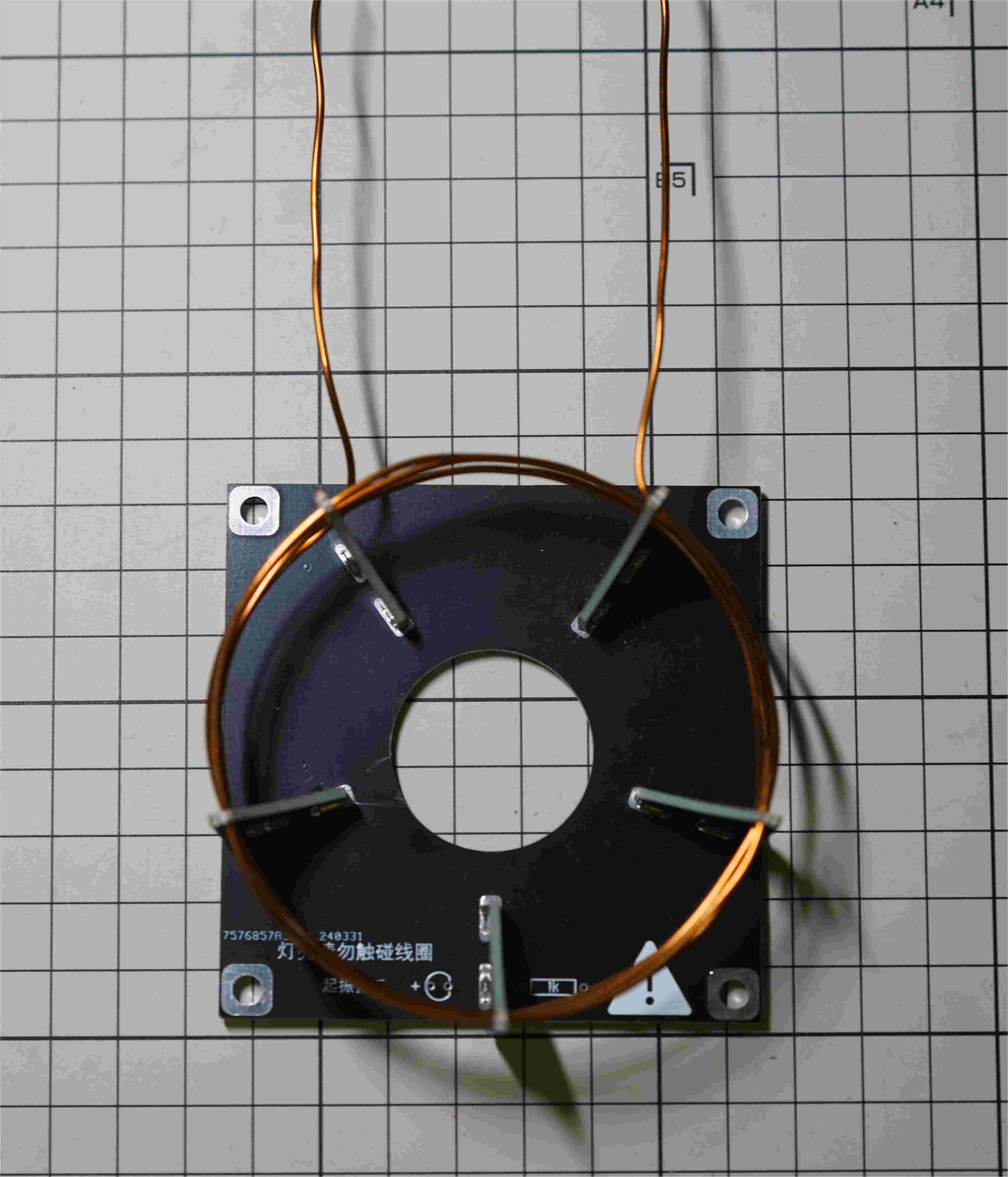
    - Thread the enameled wire through the small holes from top to bottom, a total of four turns. The holes are relatively small, and threading can be done by pushing and pulling.

  • 3
    Make a power supply with current limiting protection

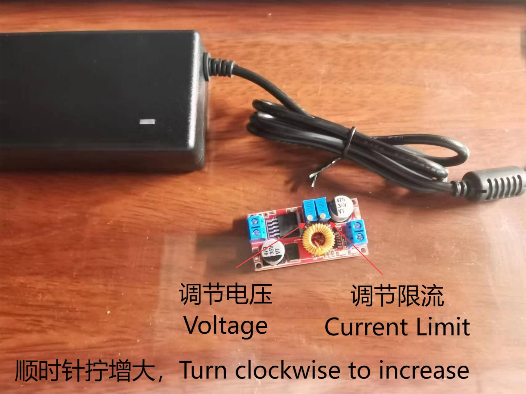
    Make a power supply with current limiting protection (this step can be skipped if you already have an adjustable power supply), prepare a 24V power supply and XL4015 current limiting module, cut the power cord, connect the module in series in the middle, turn the potentiometer for adjusting the output voltage of the XL4015 module clockwise to the end (there will be a clicking sound when turned to the end), and turn the current limiting potentiometer to the 3.5A position. The method to determine the position of the current limiting potentiometer is: set the multimeter to the 10A current range, insert the test leads into the 10A hole, touch the two test leads to the output (at this time, the output is shorted, there may be electric sparks but it's okay), the value displayed on the multimeter is the current limiting value of the current limiting module. Note that using a power supply without current limiting can easily burn out the MOSFET, you must connect the XL4015 module in series before connecting power. If you already have an adjustable power supply, you can skip this step. In the picture below, the potentiometer on the left side of the module is for adjusting the output voltage, and the potentiometer on the right is for adjusting the current limit. Turning clockwise increases the value.

    - If you are using an adjustable power supply, please use the current limiting mode (CC), set the output voltage to 24V, and the current limit to 3.5A.

View all 8 instructions

Enjoy this project?

Share

Discussions

Similar Projects

Does this project spark your interest?

Become a member to follow this project and never miss any updates