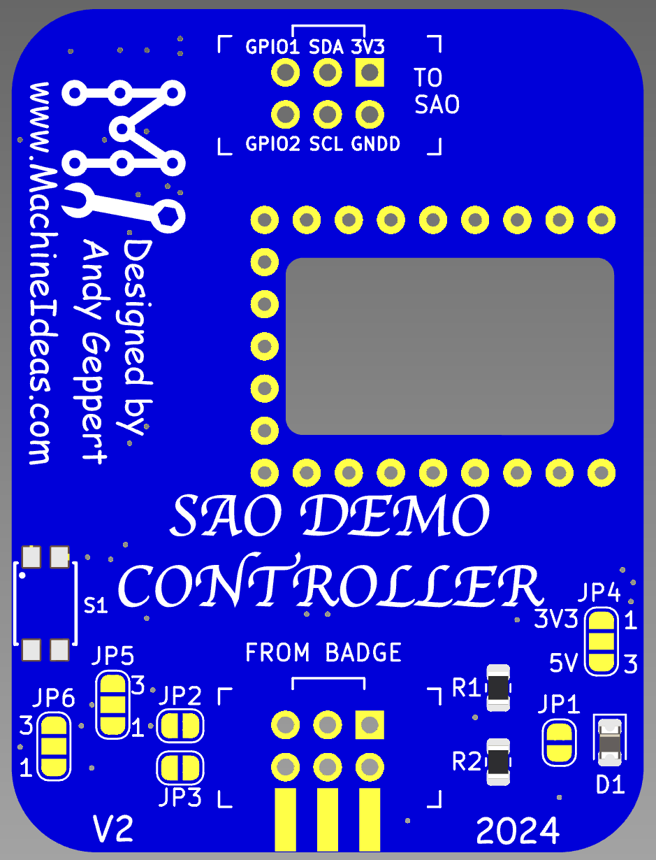
After some hands on experience with V1, I've decided to enhance the design and squeeze in another round of boards before Supercon. These are all feature additions which preserve V1 functionality. Front side:

The changes are:
- SAO output moves to the top edge to make it easy to access the back of our SAO while still plugged into the demo controller. This helps with bring-up of your SAO.
- The RP2040-Zero moves to the front face of the board for easy access to it's buttons and RGB LED.
- Power management is improved with a diode to block current flowing from the USB C port of the RP2040-Zero back into the badge.
- Default voltage to downstream SAO is now 3.3V provided by the RP2040-Zero. A solder jumper is available to change downstream SAO power source to be VIN/5VUSB, if needed.
- Downstream SAO (and QWIIC) port GPIO1 is selectable as GP1 or 26, GPIO2 as GP0 or 27 to improve compatibility with different SAOs that my brother and I are working on.
- Downstream SAO GPIO1 and 2 can be pass-through from the badge SAO port with solder jumpers.
- Added a button to control RP2040-Zero (mode selection, if desired).
- Added a voltage divider to measure incoming power with RP20240-Zero.
- Renumbered RP2040-Zero symbol/footprint to match Waveshare documentation.
Backside:

Now I need to add a switch, 2 resistors, and a diode to the kits!
 Andy Geppert
Discussions
Become a Hackaday.io Member
Create an account to leave a comment. Already have an account? Log In.