 guilldeas
Theory of Operation
Before delving into the troubleshooting and repairs let's first lay the theory of operation for the device, say that you'd like to drop a fixed amount of voltage between your input and output, your first approximation might be to employ something like a voltage divider
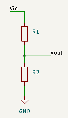
However this simple solution comes with it's own set of problems, for instance you might notice that the output and input impedances are not matched
This might prove problematic if we want to attenuate a HF signal where cable impedance plays a big role, thus giving rise to an additional loss in power due to mismatched impedances and skewing our desired attenuation. One quick fix would be to set an additional resistor in series with the output such that equal impedances are seen from both sides
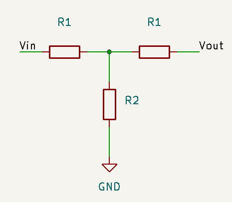
If we match both resistors at the input and output we would have achieved our goal of equal output and input impedance, say that we use 600Ω coax at our lab, we could employ a set of values R1, R2 such that
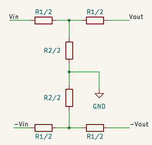
We can make further improvements on this design though, say that we want to attenuate our signal to a really low level (the HP4436A might produce outputs as low as 10µV for a 1V input at the highest attenuation!) we should then concern ourselves with signal quality, very few amounts of input noise could completely throw our Signal to Noise Ratio. One way of fighting coupled noise is to implement a balanced line, a balanced line carries 2 signals, one inverted and one normal, this means that the T-pad attenuator must be duplicated but with the added benefit that any common noise that might couple to both lines will be eliminated at the measuring end when the inverted line output is inverted once more and summed to the non inverted line. The reasoning behind this is signals at the end are twice inverted before summing them with their non inverted form which yields a coherent sum, however noise coupled during signal transfer is only inverted once before summing it against itself which effectively cancels it.
This kind of configuration is refered to as an H-pad attenuator and can be seen below, we can verify that by halving the resistances and duplicating the circuit we still preserve our input and output impedances. Just by looking at the circuit however we can see that the circuit accurate behaviour relies strongly in how matched the resistors are between each other. A total of 6 resistors need to be matched for it to work, this will be relevant later.
Our last modification will consist in making this attenuation tunable, say that we find a set of R1 and R2 resistors that drop 100dB, we could build a different attenuator with resistances R3 and R4 such that it's output and input impedances are the same (600Ω) but it's attenuation is only 0.1dB. Setting them both in series would result in a total system gain of -100.1dB. We can finally choose whether to drop 100 or 100.1dB through a set of bypassing switches like so:
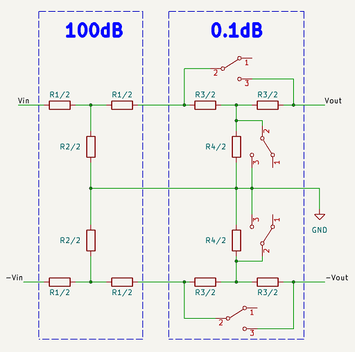
This is in essence how the device operates, a network of 12 H-pad attenuators in series (4 per decade) can be bypassed or not to configure a certain attenuation with great precision and noise immunity. If you wish to better understand the theory of operation for this device you may play with the LTSpice schematic I built attached on the files section for this project.
The Mechanical Problem
As we've explained in the previous section there are many switches to operate to set each decade of attenuation, 16 to be precise, we should then have a way to link a certain digit in our decade to 16 on/off positions. The mechanism behind this is mechanical, each rotation of the decade dial would rotate in turn a shaft with multiple cams or lobes positioned along its length. These cams engage with a series of levers, which in turn actuate the switches by sliding in or out a dielectric between two contact depending on the axial (or rotational) position of the shaft.
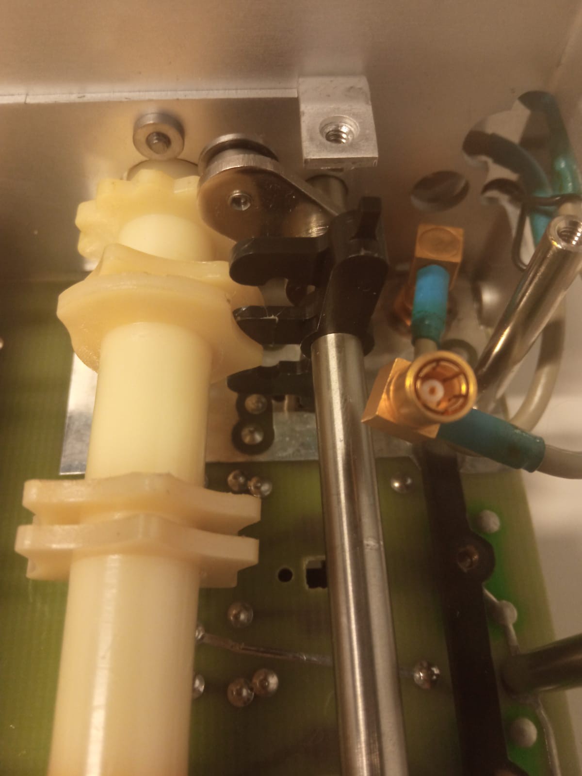
Below we see a disassembled view of the shaft and cams (beige) and lever (black), the lever would swivel left and right a small amount depending on the cam position for a certain digit. The small square latch protruding on top of the lever would engage with a piece of plastic on the PCB on top that would be the mechanism for the switch.
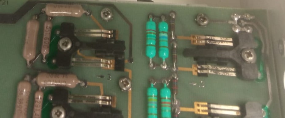
Below an image showing the switches (black) these would slide left and right driven by the swiveling movement of the small shaft on the levers. When the switches slide thin plastic films may slide in between the PCB copper pads and spring contacts (metal strips) breaking their contact and thus bypassing or not a certain H-pad attenuator for different digits on the decade dial.
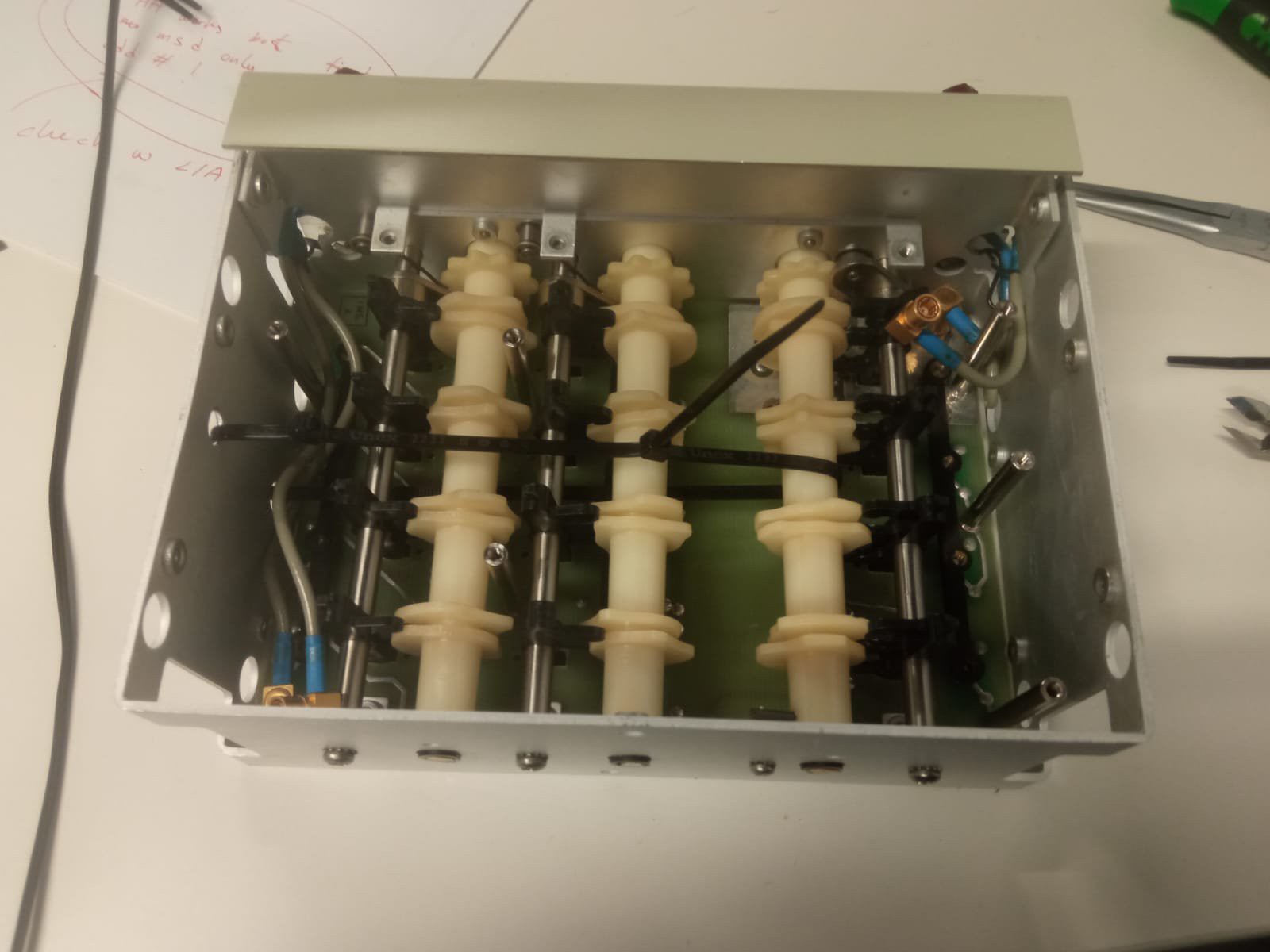
As you can see the machines basic functionality is resting on the shoulders of many different thin plastic pieces forcing themselves into each other. After 40 years many of the levers latches had broken and one of the shafts had buckled to the point where it could not turn beyond a certain digit.
To solve this a pair of zip ties secured ot a couple of drilled holes in the enclosure (left) relieved the tension on the shaft (right) allowing it to spin freely once again.
As for the latches I decided to cut a paper clip into small rods, then with the help of a soldering iron I would drive the heated rods into the levers to substitute the latches. (not pictured)
This took care of the mechanical issues so I decided to test that the attenuation of the device was in spec.
The Electronics "Ghost" Problem
Testing a machine like this can prove complicated though, any good enough hand held multimeter could test the whether the first 60dBs of attenuation are accurate, place a 1V signal and the input and measure the output, finaly find the attenuation like so:
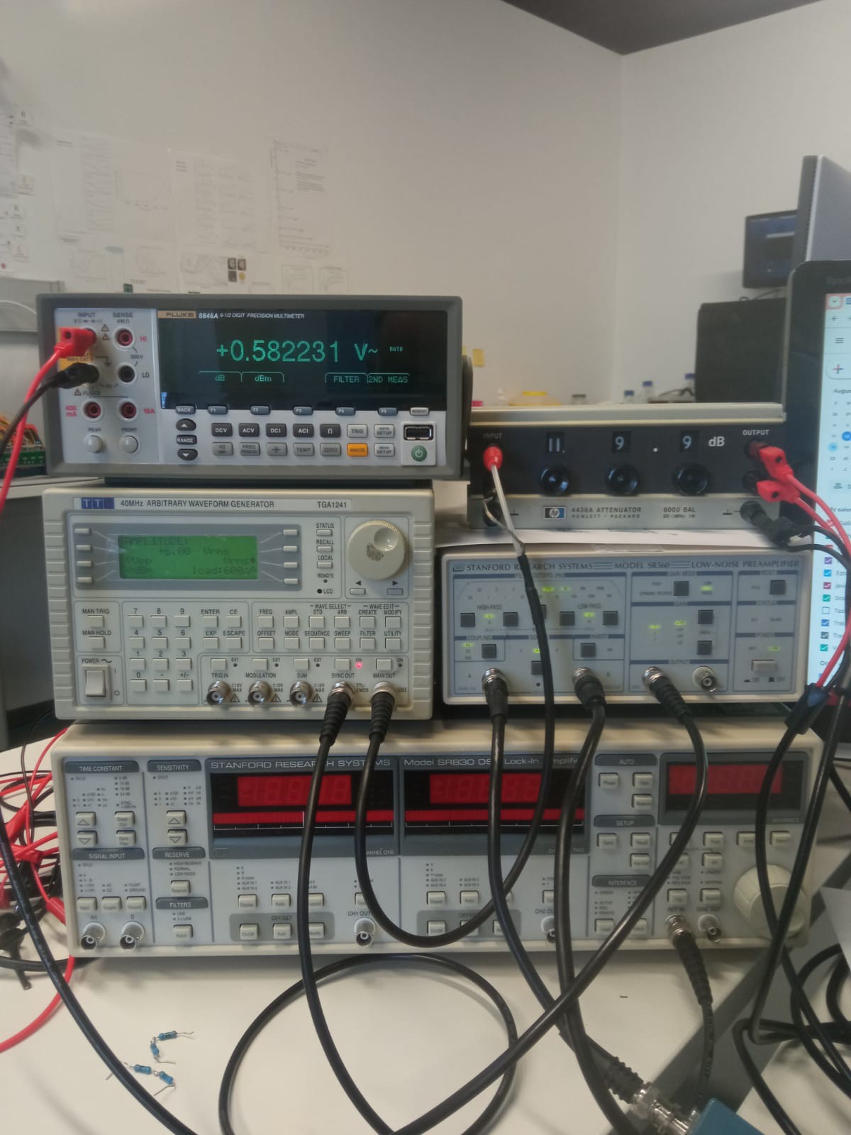
Measuring the output voltage beyond 60dBs of attenuation gets complicated, output voltages may drop below the mV range well into the μV, we then need a more precise measurement. During this time I was lucky enough to be working with such a machine, an SR830 lock-in amplifier (LIA), the theory of operation for such a device is out of the scope of this project but just think of it as a black box that computes the Fourier Transform for a given signal + noise and spits out only the signal power at a specific frequency of choice. Then if we run a signal of known frequency though our attenuator, even if the attenuated output is so small that it's completely drowned in noise, we can recuperate the output signal power just by telling the LIA to compute the FT at the signals frequency.
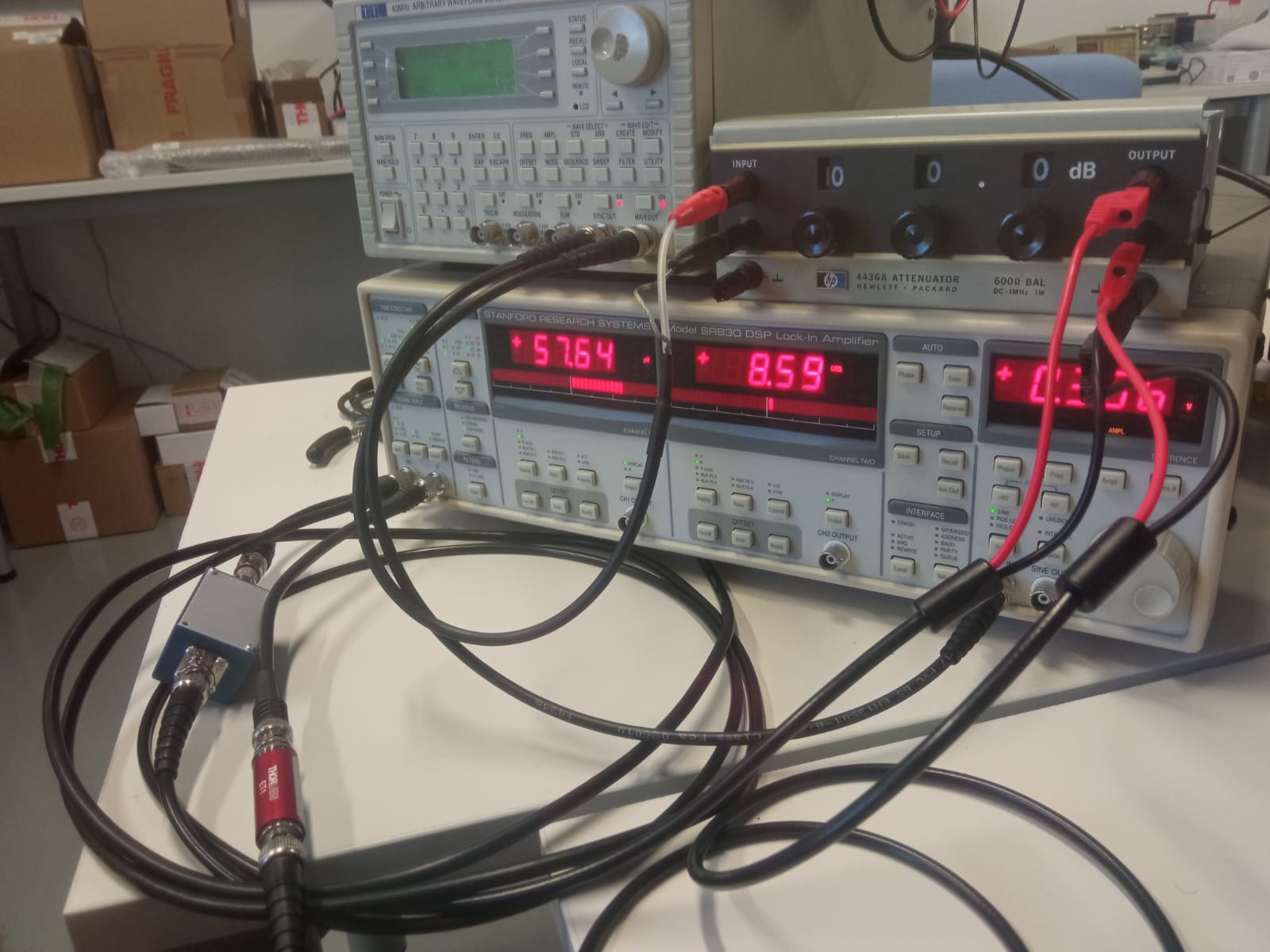
You may look at this image and recognize there are some unexplained elements in the setup. Those extra couple cables and inline feedthroughs (red and blue) form the ballanced line and impedance matching circuit.
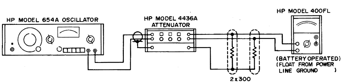
The setup described on the schematic below was roughly followed like so: A 600Ω signal generator outputs a signal with a certain level (1Vrms), our source is not ballanced so we have to make do with an unbalanced conneciton at the input, we tie positive to positive input on the 4436 and negative to negative input. However, unlike the schematic below, we have to leave the 4436 GND floating at the input which negates the BNC shields protection against capacitive coupling, I wasn't too concerned about this because signal level at the input is relatively high compared to noise while at the ouput, where signal is dangerously low, we are able to use a ballanced line, here's how:
We leave the LIAs inputs floating and take a differential measurement (LIAs channel A - channel B), we tie +A to positive 4436 output and +B to negative, finaly we tie both BNC shields to 4436 ground input, now any common noise will make both the positive, negative and GND lines drift "upwards" or "downwards" collectively wihtout an effect on signal integrity.
Finally let's adress the feedthroughs, since the LIAs inputs are high impedance we need to bring that impedance down to match the 600Ω expected by the 4436, to do so we simply shunt a 300Ω low TOL resistor on each LIA channel, A and B, since their impedance is so high we can assume the equivalent resistencance to be basically 300Ω each, 600Ω in total. Finaly I encased the resistors in metal feedthroughs to minimize noise coupling.
Note: Resistors where hand-picked and matched to a really low TOL of 0.01%, see resistance check sheet on AC Performance Test.xslsx]
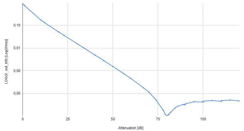
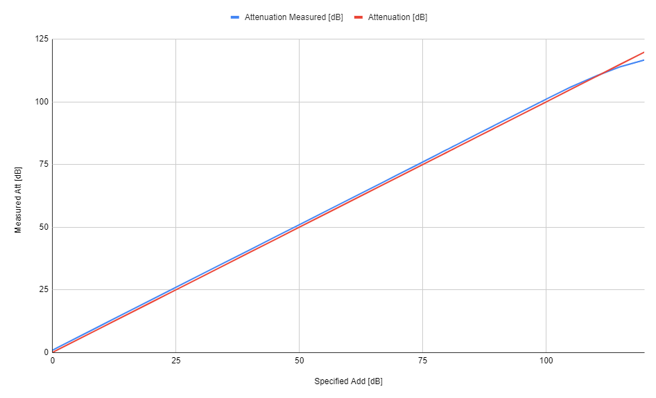
With the setup now ready for measurement I took the first readings, I swept the attenautor down from 0 to 119.9dB attenuations in 30 steps but the readings were off.
A different way to visualize them would be to compute the attenuation for each value knowing the input and output voltages like we explained above, then plotting it against the expected attenuation
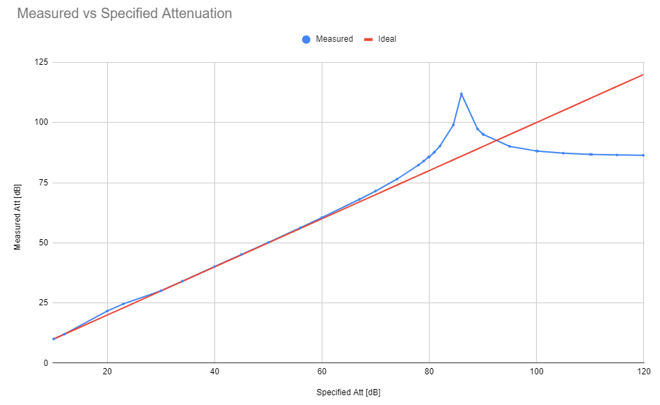
Something was deffinitely off, I went to the service manual and it suggested measuring the contact resitance at the switches, a value above 300mΩ would be anomalous, remember how crucial it was for the resistors on each H-pad attenuator to be matched? This is what the HP engineers want us to check now, contact resistance might add series resistance to a certain H-pad and throw off the attenuation.
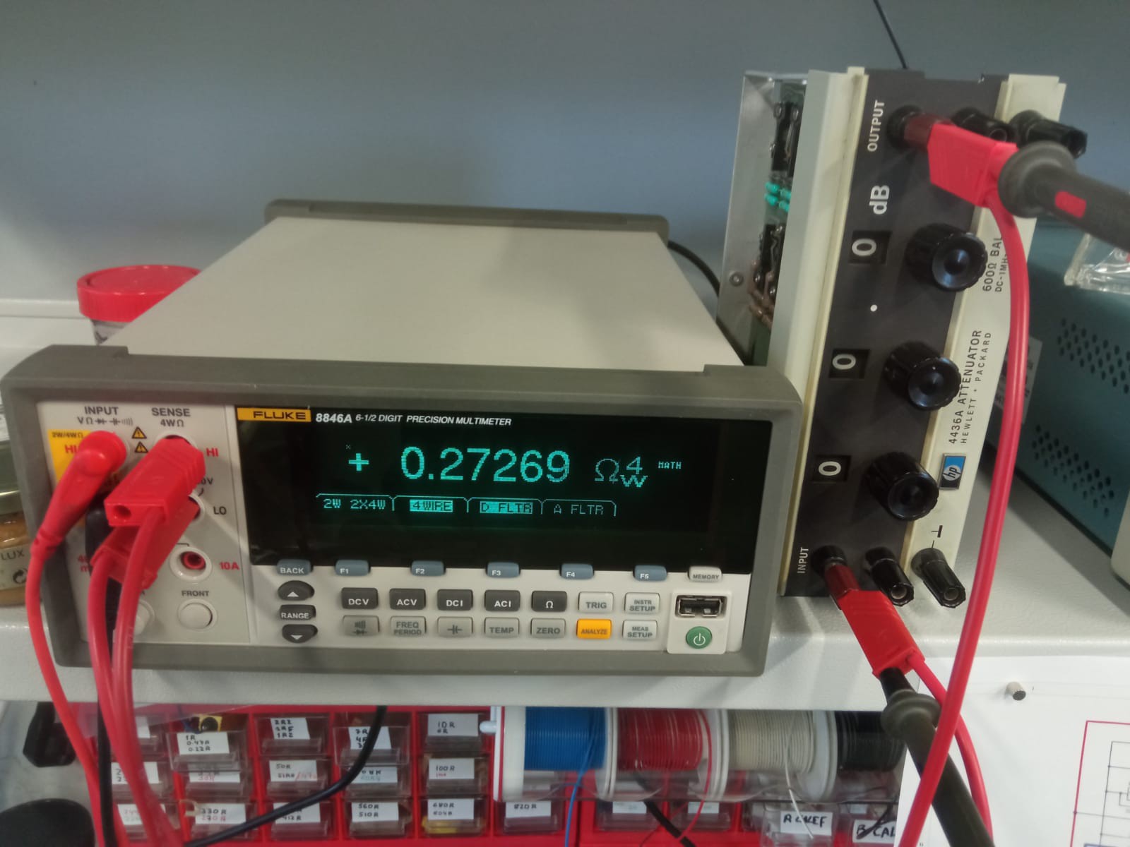
To check the contact resistance we simply set the attenuation to 0.0dB thus bypasing all attenuators but allowing the current to flow through the switches, we then measure the resistance from positive input to output and repeat for the negative path. Using a good multimeter capable of zeroing and doing 4 wire measurements is important when measuring such low resistances. Employing an 8846a Fluke DMM I got a 400mΩ measurement which is slightly off spec, at this point you might've seen the rusty contacts on the close up of the switches and think like me "yeah that tracks, contacts are rusted and the attenuation has gone haywire" that prompted me to give some love to this old machine, I sanded down both sides of each of the 48 switches, I also added some pressure to some loose spring loaded contacts by desoldering the metal strips and bending them back up again.
With a couple afternoons of fine "wrist grease" I got the contact resitance back in spec:
Sadly and to my despair the problem persisted, attenuation at the lower settings was not working. This machine is in essence pretty simple though, there are switches and then there are resistances, let's now check the resistances, perhaps some of them had drifted with time.
I made use of the helpful switches and armed with the 8846 DMM I went to testing, I isolated each of the resistors that were in use on the malfunctioning 100dB configuration separators between the contacts and taking a reading. This showed that a couple of resistors had indeed drifted slightly above spec [see resistance check sheet on AC Performance Test.xslsx], before replacing them with some very hard to find particular resistors I decided to throw all of these resistance measurements into LTSpice and simulate the whole 4436 on the 100dB setting, yes I felt a bit cornered at this point and was in desperate need of a sanity check.
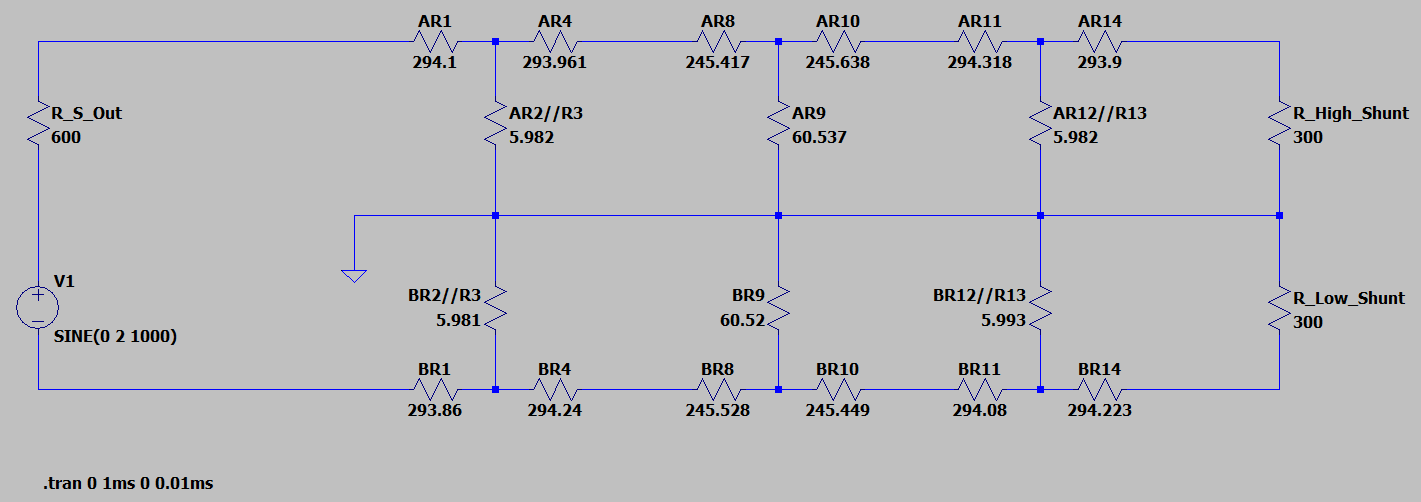
Once again to my surprise the simulation showed that the attenuation should fall pretty close to 100dB for such a small deviation in resistance, however I was not seeing that.
At this point I was totally lost, the machine was working in theory but not in practice, this usually points to an error in the instruments but I had borrowed the LIA from a laboratory who had assured me the instrument had worked flawlesly not so long ago, the LIAs configuration was verified to be correct by a fellow researcher...
I had to check though, I had to somehow measure the attenuation without the lockin, at this point I had to throw everything I had at this pile of old resistors. I spent a couple more after-work hours setting up a new measurement, I borrowed an SR560, a low noise preamplifier with extremely high gain and, most importantly, differential floating inputs that would allow me to perform a balanced measurement. I tied the output to the precision DMM and prayed that the total system gain was high enough to resolve those pesky µV.
Here's a look into the final pile of instruments, threatening to buckle the legs on my office table
I finaly, nervously, took the measurement...
Bang on and within 1dB of spec...
Ad Verecundiam
Or argument from authority is a fallacy in which one is trusting of the argument from an authority simply because it is an authority. One could fall for this fallacy so much even as to spend a whole week and a half of after-work hours chasing down a symptom that never existed.
Despite of what my colleagues had told me the lockin amplifier second channel must've been faulty and since the team using it only uses the first input noone had verified that it was actually working but the researchers affirmed it had no issues and I believed it as fact.
Oh well, a second latin saying comes to mind "Ad Astra Per Asepera" or "the path to the stars is full of hurdles".