As mentioned previously, the paddle shifter project was developed to improve the competitiveness of the UH FSAE car in the SAE competition. With greater control of the vehicle, the driver can focus better on the track during autocross to improve their lap times instead of constantly shifting with a lever. This improvement was applied by Ferrari's Formula 1 team in 1989 which began the paddle shifter standard in F1 racing [1]. In modern F1 cars, paddle shifters are integrated into the steering wheel, and the paddles themselves, when sold separately, cost more than $700.
Figure 1: $700+ Ferrari F8 Paddles for Paddle Shifter
For university FSAE teams competing in the annual SAE competition, the cost of paddle shifters is impractical from both a competition and budget perspective. The SAE competition evaluates teams not only on dynamic events such as autocross and acceleration but also on a business presentation, which includes the cost to manufacture the car. While paddle shifters can offer a competitive advantage, they must be implemented affordably without sacrificing performance.
For the UH FSAE team, the paddle shifters will be paired with a pneumatic system that controls upshifting and downshifting. When the shifter is activated, electronic components will monitor engine RPMs to ensure shifts occur at safe levels. Once the correct RPM is reached, the pneumatic system will apply pressure to pistons that initiate the gear shift, repeating this process for each gear change. Additionally, the paddle shifters must be integrated around pre-existing components and operate while the engine is running, presenting critical physical constraints to consider.
The entire system, which includes the paddles, electronics, and pneumatic components, must not exceed a maximum weight of 50 lbs to avoid increasing the weight-to-horsepower ratio. The paddles themselves need to withstand a force of 121.1 kg, which represents the grip strength of the 95th percentile of men aged 20-24, as required by the FSAE rulebook. To account for safety, the paddles will be designed to handle 20% more than this force.
Additionally, the paddles must be positioned at least 24.88 inches from the driver to ensure accessibility for the 5th percentile of women in both upright and reclined driving positions. Paddle shifting time is expected to be 0.4 seconds, based on testing during vehicle operation on track. The system must also allow for easy attachment and detachment within 10 seconds for maintenance or replacement.
The system's power usage is still to be determined, as it must align with the vehicle's limited power from the stator, and the available space for the paddle shifters on the steering wheel is restricted to 126 cubic inches (9" x 7" x 2"). The total budget for the system is capped at $900, though efforts will be made to reduce costs where possible. In addition, the force required to move the lever and shift the engine's gears remains to be determined, and the system must be designed to withstand engine-convected heat of up to 210°C, ensuring the reliability of both the pneumatic and electronic components in such conditions.
| Constraint | Value | Comments |
|---|---|---|
| Maximum Weight of the entire system | 50 lbs | The system includes paddles, electronics, pneumatic components |
| Maximum Applied Force Paddles Can Withstand | 121.1 kg * 1.2 | The grip strength of the 95th percentile of men aged 20-24 is 121.1 kg, per the FSAE rulebook it must accommodate |
| Minimum Force Required to Activate Paddles | TBD | |
| Minimum distance of Paddles from the driver in the upright or reclined position | 24.88 inches | For the paddles to be within reach for the 5th percentile of women in a functional grip position |
| Paddle Shifting Time | 0.4 seconds | Measured by recording the driver operating the vehicle in a track |
| Time for paddles to attach/detach | 10 seconds | |
| System Power Usage | TBD Watts | Vehicle limited in power by stator, need to verify the extra power available |
| Paddle Shifters Available Space | 126 in^3; 9" x 7" x 2" | Volume/Dimensions available for paddles on steering wheel |
| System Cost | $900 | Total budget available, want to reduce price as much as possible |
| Force required to move lever to change gears on engine | TBD | Need to know force required to be able to shift the gear on the engine |
| Expected temperature convected by the engine | 210 °C | Pneumatics and electronics will be affected by the convected heat transfer |
To address the key physical challenges before executing the design, we will rely on simulations and calculations. To determine the external forces our paddles can withstand, we can use software like SolidWorks or COMSOL to simulate constraints such as mounting points, material weight, and forces. This will allow us to generate a Von Mises diagram, identifying areas of our design experiencing the highest stress. A crucial aspect of this analysis is applying realistic constraints to the CAD model to accurately replicate the real-world conditions the system will face. Based on the results, we can make CAD model alterations to prevent high-stress concentration areas, identify effective material choices, and improve factors of safety.
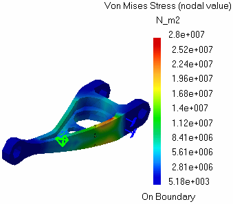
Figure 2: Sample Von Mises Diagram
Additionally, thermal analysis will be conducted on the pneumatic components to assess the impact of engine heat on flow rate, pressure, and structural integrity. These simulations will help us anticipate how the system will perform in real-world conditions. Based on this result, we can identify areas that will have the greatest heat transfer to know where insulation could be needed.
To further validate our simulations, we can calculate the force required to move the engine's shifter based on available dimensions. From there, we can determine the pressure needed for the pneumatic pistons, optimizing the cross-sectional area for efficiency. Additional calculations will be made to insulate wiring and pneumatics from engine heat, helping us choose the optimal insulator thickness to minimize heat transfer.
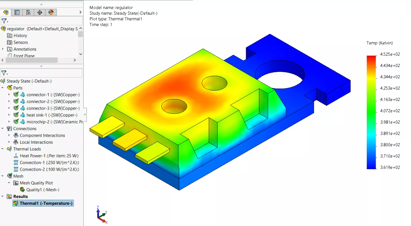
Figure 3: Thermal Study Using SolidWorks
Additional challenges in the design include determining the exact mechanism that will use the pneumatic pistons to actuate the shifter on the engine for upshifting and downshifting. This will likely require a separate CAD design to specify how the pistons will interact with the shifter lever. Since the pistons will be located behind the engine, the available volume will be constrained by the chassis and powertrain components, further complicating the design.
Other important considerations include the method for mounting each component in its respective location: the pneumatic pistons to the chassis and shifting lever, the paddles to the steering wheel, and the electronics to the vehicle. Additionally, since we are using pneumatics, we must account for the inclusion of a compressor and air tank reservoir. These will introduce additional weight, cost, power requirements, volume constraints, and the need for mounting points.
Measuring a successful outcome will begin by verifying, outside of the car, that the paddles, electronics, and pneumatic system function properly for both upshifting and downshifting. Once we confirm that the programming works as intended and the compressor fills the tank reservoir to activate the pistons, we can then validate the simulated forces and calculations using the prototype.
Discussions
Become a Hackaday.io Member
Create an account to leave a comment. Already have an account? Log In.