 Thomas Flummer
I had these boards populated with all the SMD parts and for this, the board was panelized in a 2x2 configuration, with a frame and "mouse bites" (row of small holes in the PCB), to allow separation.
I positioned the mouse bites outside the edge cut circle, so that they could be sanded away after separation.
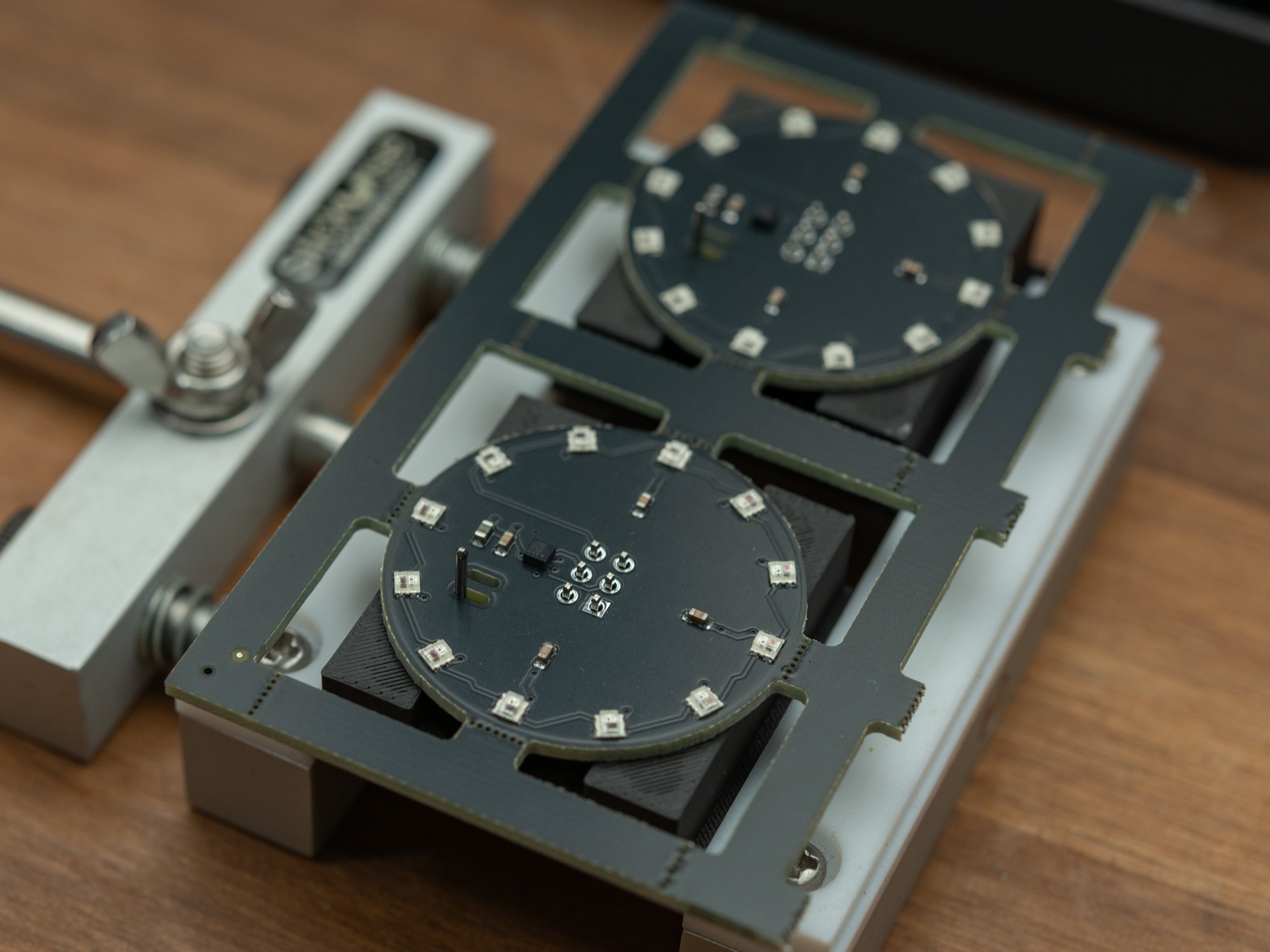
So ease the soldering of the SAO connector, I decided to first half the panels and then using a 3D printed jig, solder in the connectors, before the full separation and sanding.
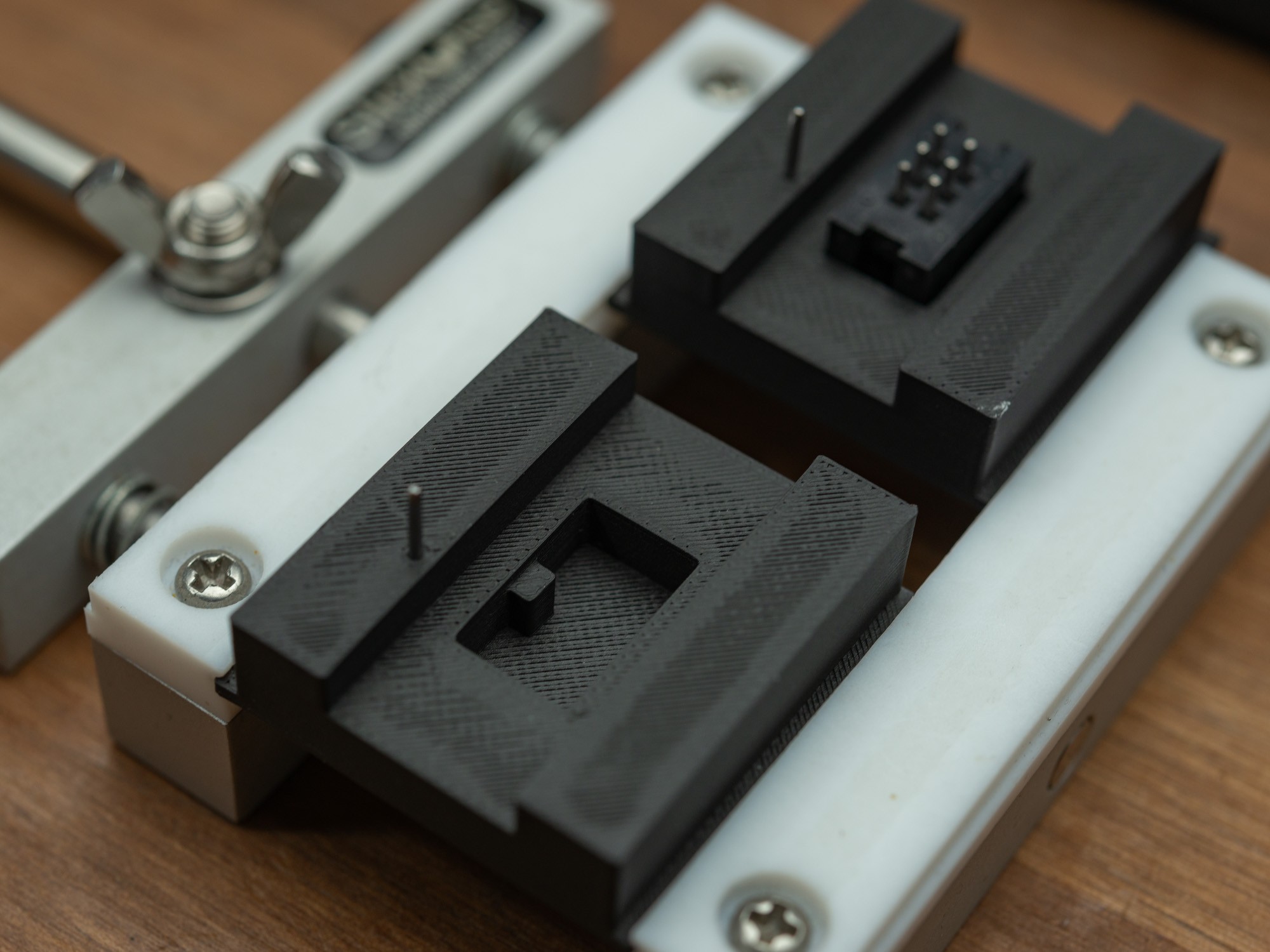
The 3D printed jig with small steel dowels that is used to align the board using one of the cutouts for the SAO leash in the PCB.
The notch in the bottom makes sure the SAO connector is oriented correctly.
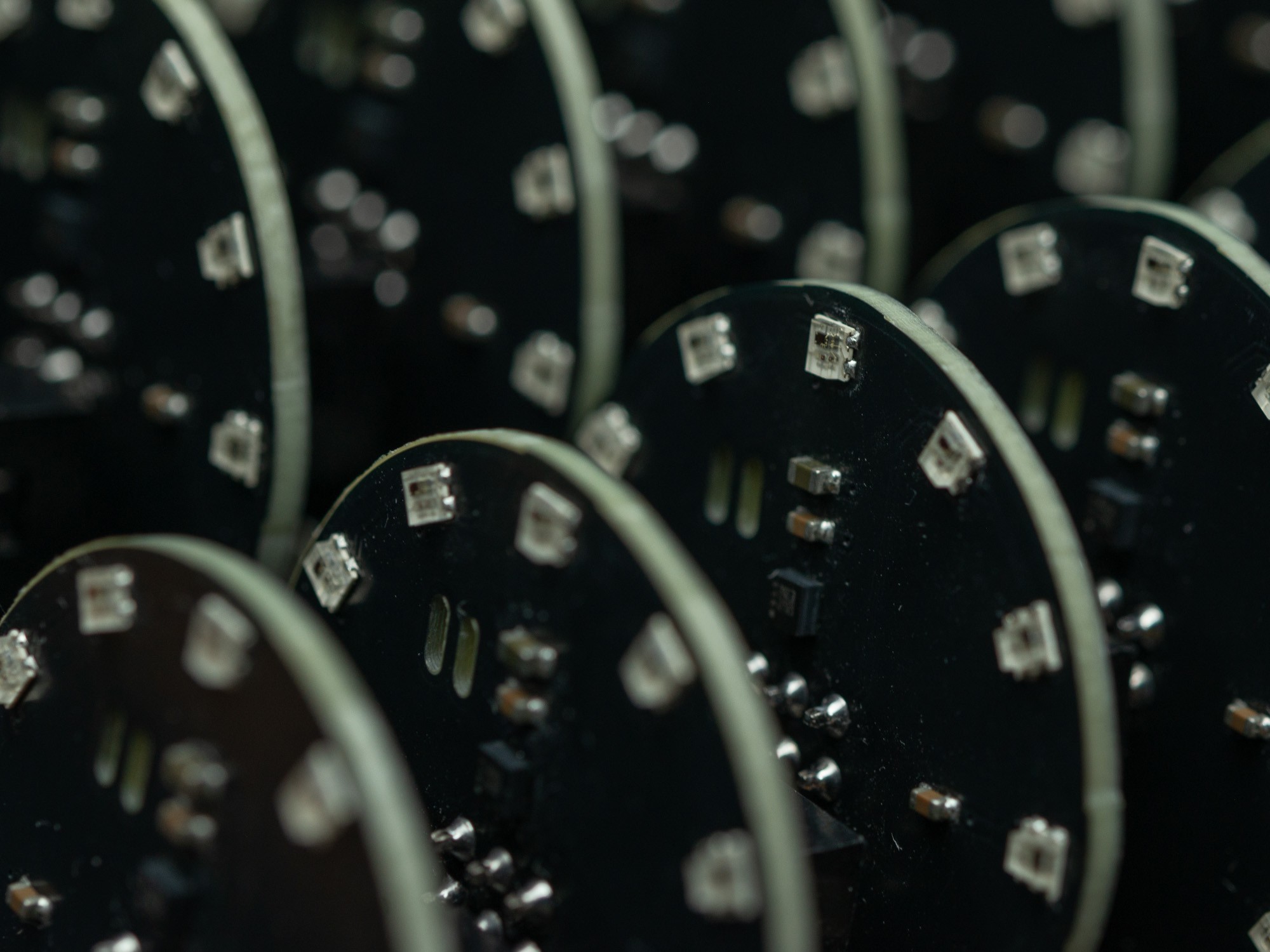
After soldering the connectors, it was time for depanelization.
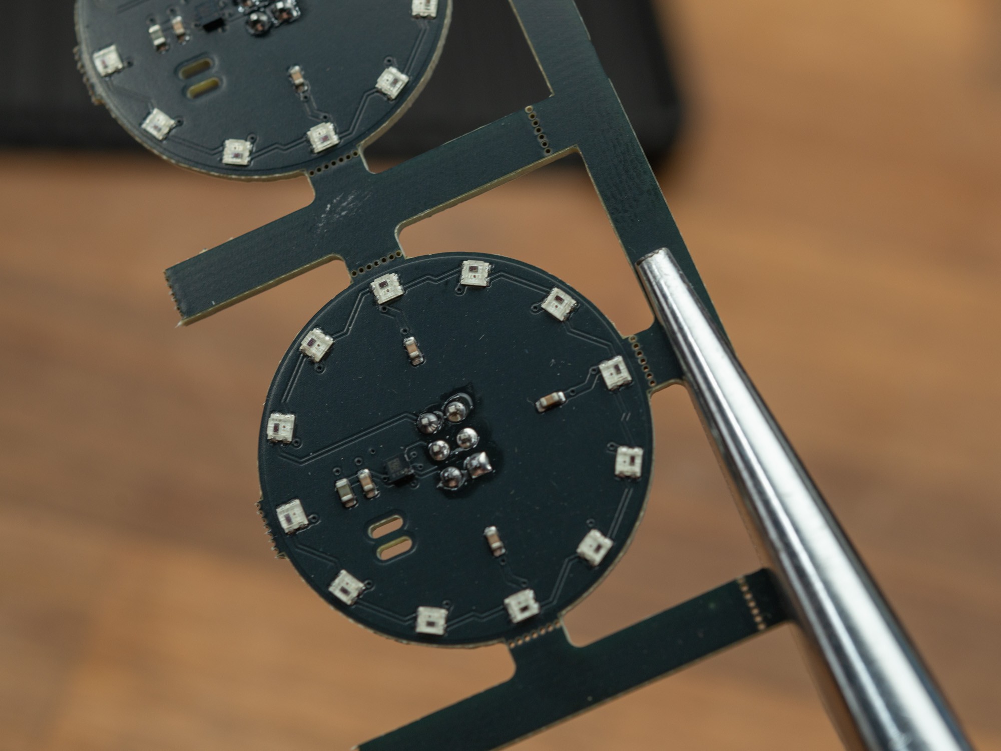
They snap relatively easy, but holding the thin rails with a needle nose plier helps a lot with a relatively clean break and protects you fingers when doing many.
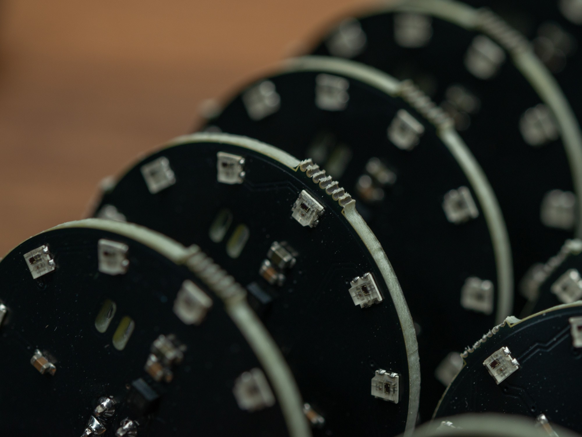
The excess PCB that was sticking out was sanded away with a disk sander. It's a bit fiddly and messy so not an ideal way, but there isn't that many options when you want a fairly clean outer edge on a circular PCB and want machines to assemble the small parts.
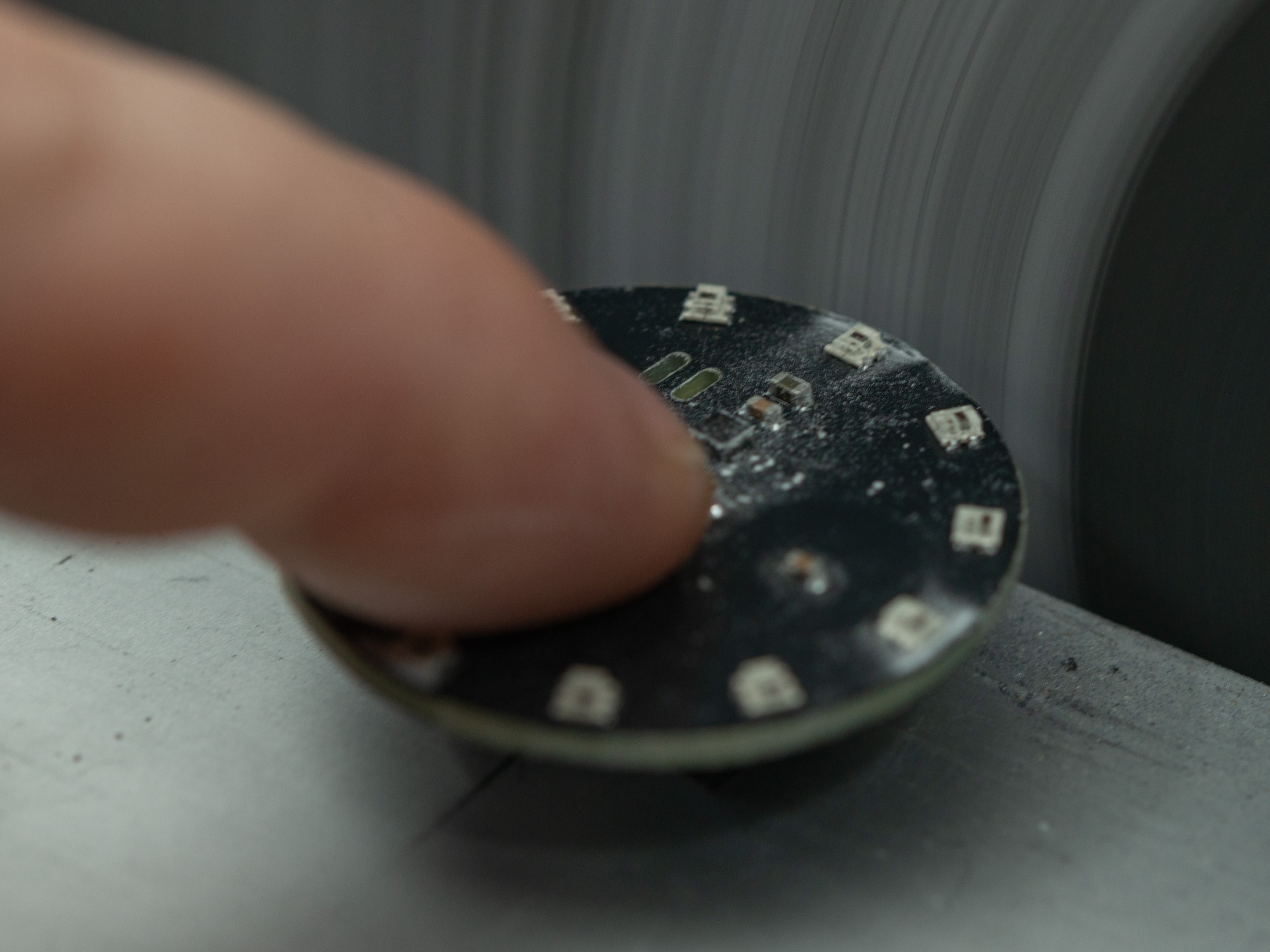
It's not always perfect but should be good enough to not hang on to peoples clothes and maybe get ripped off.
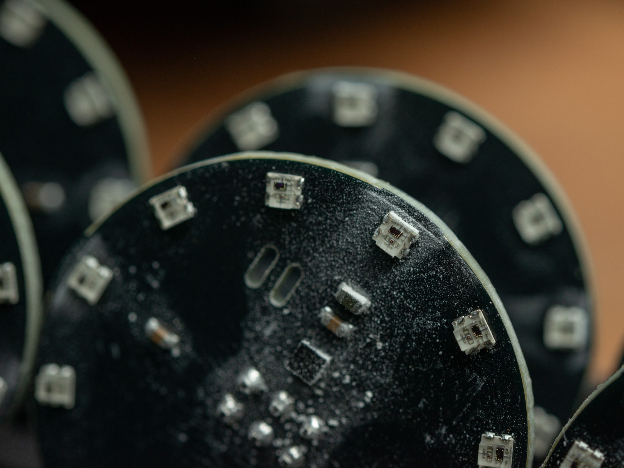
They end up pretty messy, after being sanded in 4 spots, so to get rid of that and the flux from the soldering, I decided to give them a wash in isopropyl alcohol (IPA), and dry them with paper towel.
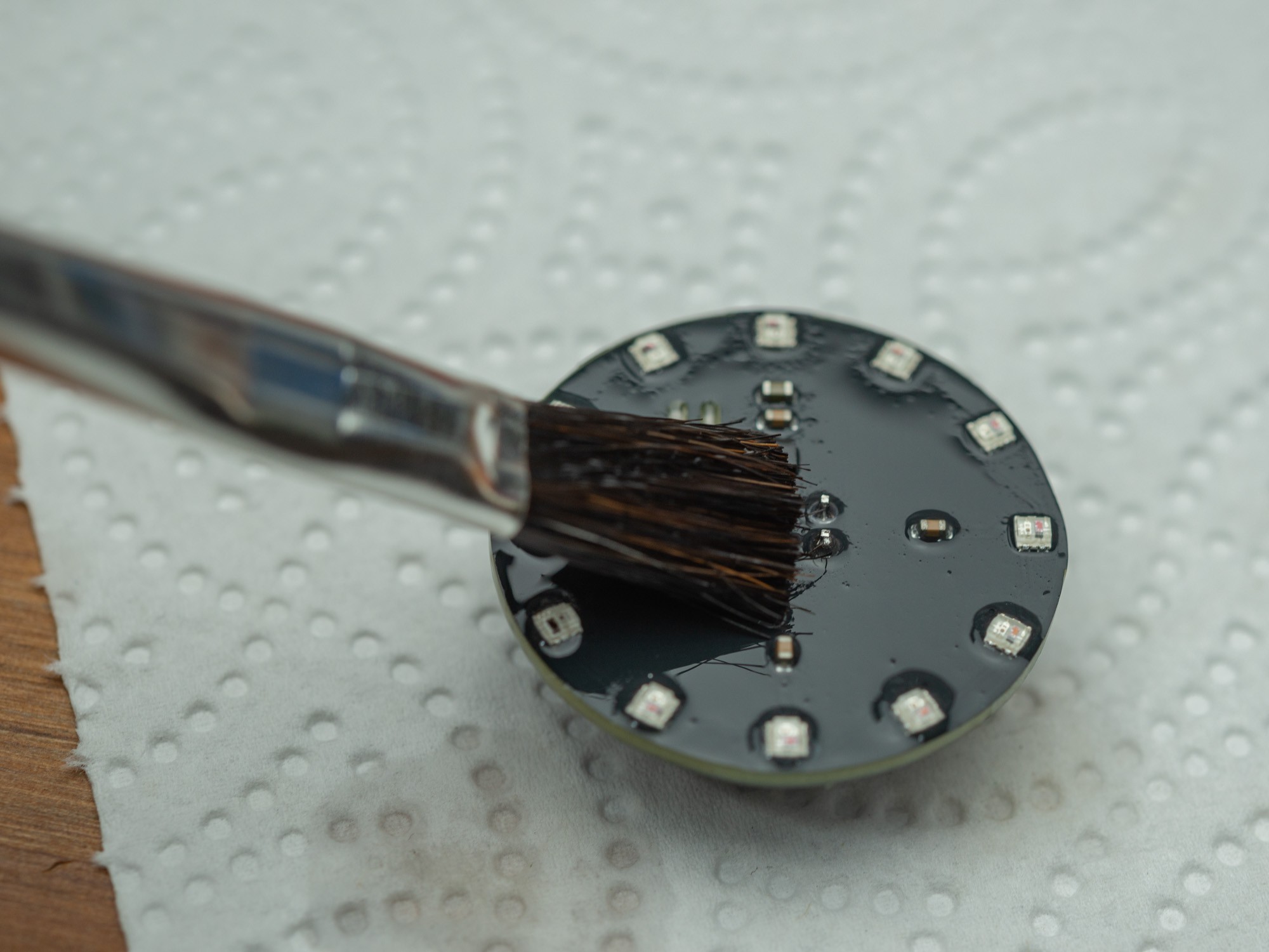
Looks better after cleaning.
Discussions
Become a Hackaday.io Member
Create an account to leave a comment. Already have an account? Log In.