Our first attempt at building a 5/3 closed-center control valve.
After watching videos and reading articles about control valves, we understood how they work. Basically, you move a shaft with a piston to close or open the passage of air or fluid.
This is our first design:
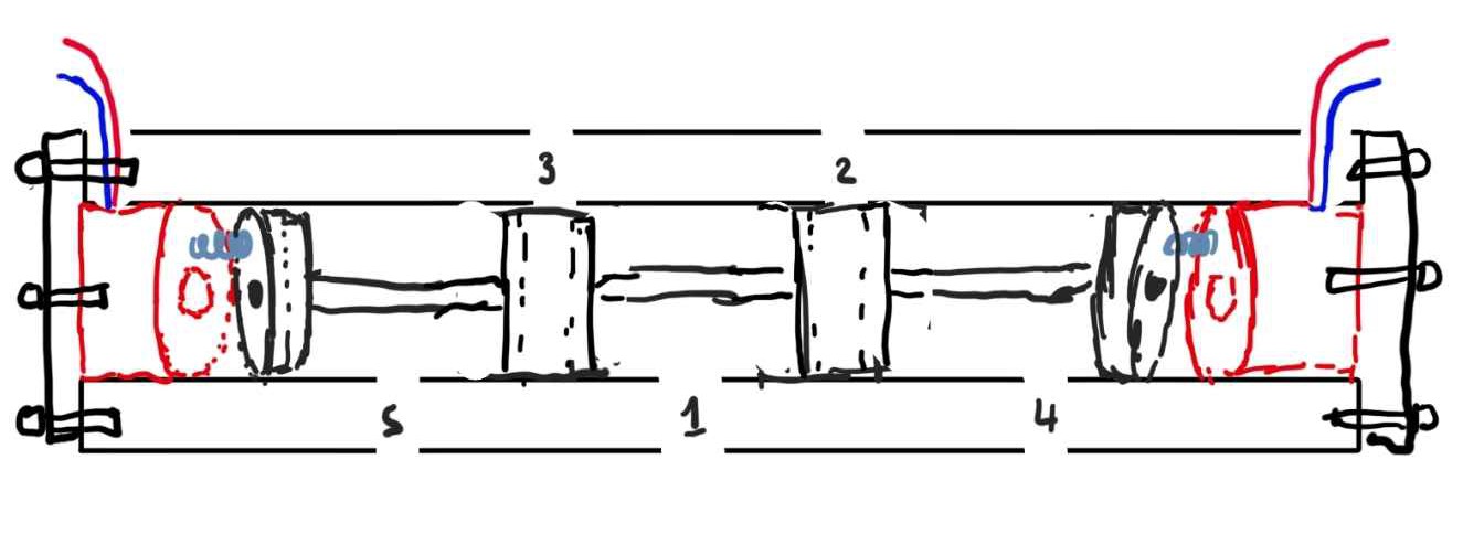
- Compressed air inlet
- Air Oultet
- Air Outlet
- Exhaust port
- Exhaust port
The valve consists of two electromagnets on each side of the valve, two powerful permanent magnets at each end of the shaft, and two compression springs between the permanent magnet and the shaft.
It work as follow :
The shaft can be in the :
- Closed positoin (depicted in drawing)
- Right position (connecting hole 1->2 and 3->5)
- Left position (connecting hole 1->3 and 2->4)
Allowing us to control/block air flow
To move the shaft, the electromagnets will try to pull/push the magnet at each end of the shaft.
For exemple to make the shaft move :
- Left :
- The left electromagnet will pull
- The right electromagnet will push
- Center :
- The left electromagnet will push
- The right electromagnet will push
BEFORE WE CONTINUE I WOULD LIKE TO TALK ABOUT THE SEAL USED IN THE VALVE
It goes without saying that a control valve whose role is to block and direct the flow of gas or fluid has to be perfectly sealed, which is, I think, the most difficult part of making the control valve, especially because we try to 3D print it.
We used O-rings to seal the valve.
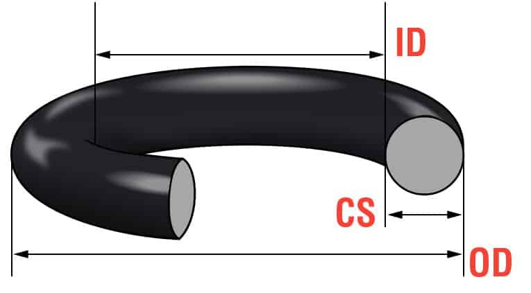
And although it sounds simple, it's also very complicated: we had to learn about piston groove design, O-ring compression, etc....
Fortunately, there were a ton of resources on how to design the groove for a dynamic application based on bore diameter and piston diameter.
Here were some helpfull website :
This is still the main difficulty encountered in valve making, as it induces a lot of friction and the need to use a lot of force to move the shaft, leading many prototypes and iterations to fail because the method used to move the shaft didn't have enough force.
Or it just wasn't sealing enought.
I made this parenthesis because I don't think I'll come back to it in the next logs because I don't find it very interesting to talk about the dimensions of an oring groove for each prototype.
Now having an idea we went on to make a first prototype :
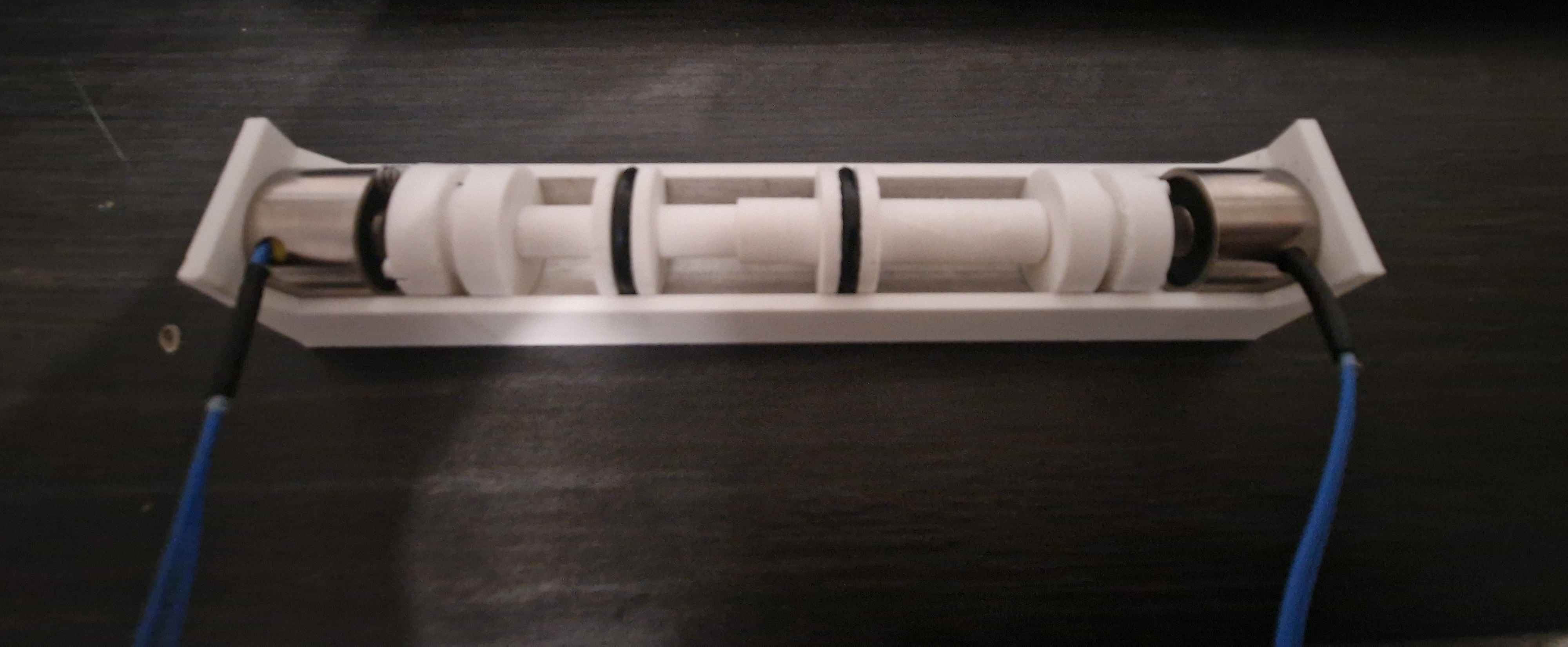
The aim of this first prototype was to see if the tree could move.
But thanks to this, we began to see the many problems with this design;
First of all, the force and distance of the pull/push:
These electromagnets were advertised for a force of 2.5 kg, but what we didn't know was that this 2.5 kg force only applied in the event of direct contact with the electromagnet.
With this prototype we were reminded of the Inverse-square law
In science, an inverse-square law is any scientific law stating that the observed "intensity" of a specified physical quantity is inversely proportional to the square of the distance from the source of that physical quantity.
For this design this means that the displacement of the shaft can only be very small <10mm, otherwise the pull/push force of the magnet cannot overcome the friction and/or spring force and cannot move the shaft.
Such a small displacement wasn't ideal because all the holes would have to be very close together, risking leakage in case the shaft didn't move exactly to the right position.
Nevertheless, here's the prototype in action:
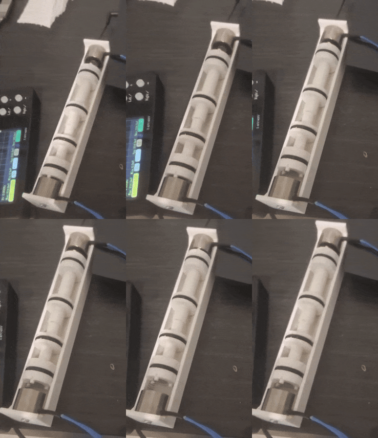
As you can see, it worked, but we couldn't use it in a real-life situation for one simple reason: friction ;
The aim of the first prototype was to test whether the shaft was able to move, but when we tried to make a second prototype of this design with a sealed housing, the magnet simply couldn't win against the friction between the seal and the bore.
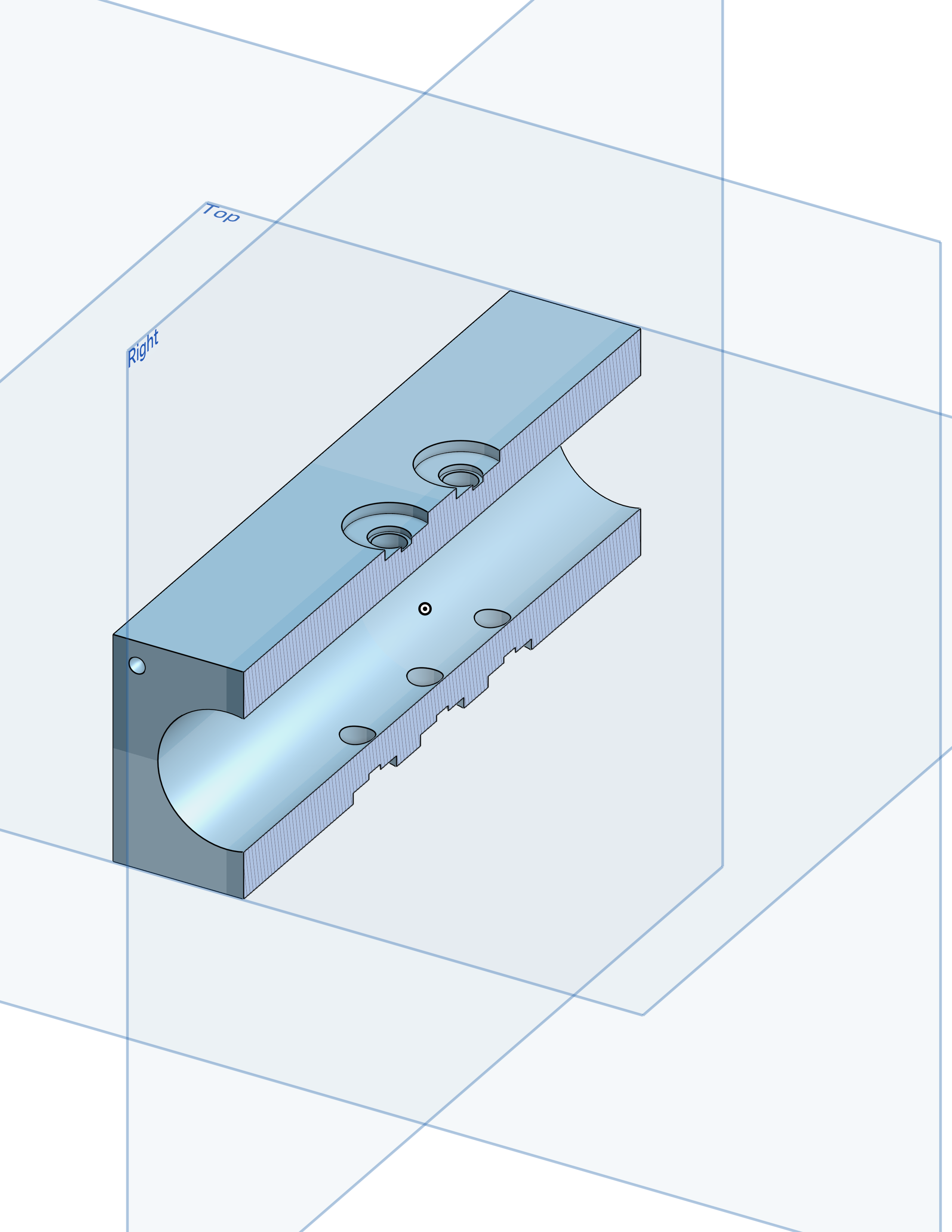
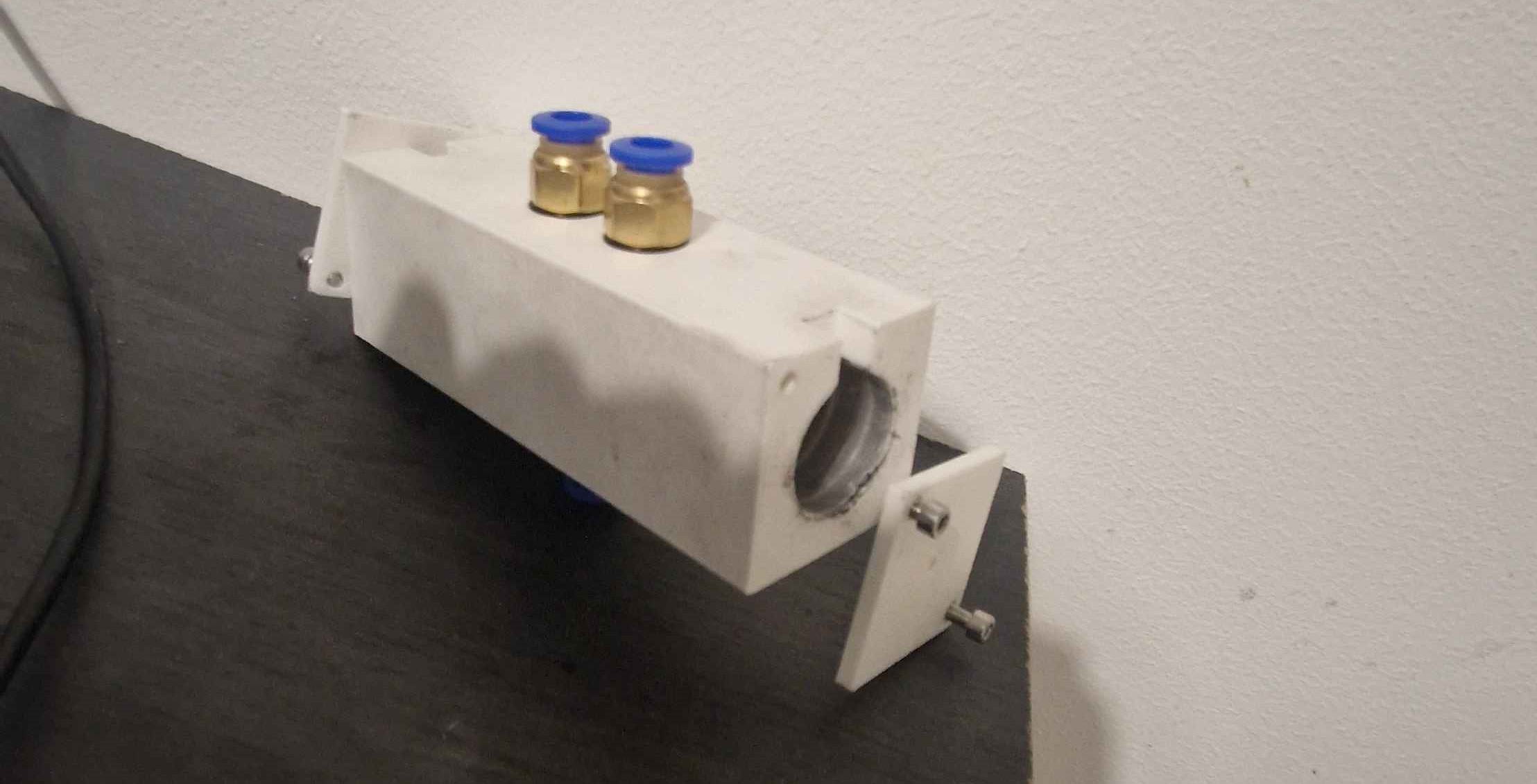
We then decided to abandon this desiign, because it had too many flaws.
 Nasser
Discussions
Become a Hackaday.io Member
Create an account to leave a comment. Already have an account? Log In.