 joon-ho.kim
First Design of the ARM
At first, we planned a laser-cut wooden frame for the arm and gripper.
This was our initial design for the arm frame :
And for the gripper :
However, we shifted to 3D printing to enable more complex shapes and greater convenience.
FINAL DESIGN OF THE ARM
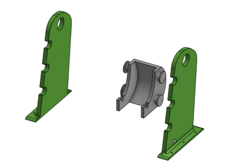
Base of the hydraulic arm
The first step in constructing our hydraulic arm was to create a sturdy base capable of withstanding the forces exerted by the other components. This base was designed to be thick and robust, allowing it to be securely screwed onto a plate.
The gray component is fixed to the green components using three aligned holes. This assembly serves as a mounting point for the actuator, enabling it to rotate. Additionally, a ball bearing will be placed in the top hole of the green component, facilitating smooth rotation between it and the central part of the hydraulic arm.
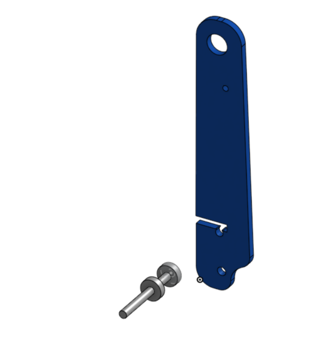
central part of the hydraulic arm
This component serves as the central part of the hydraulic arm. The stem tip of the first actuator will be secured in place using a threaded rod inserted into the small hole at the top.
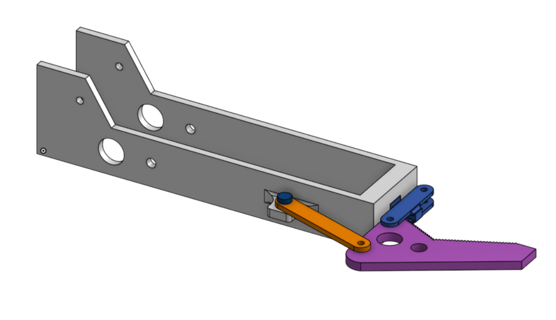
top part of the hydraulic arm
This component represents the top section of the hydraulic arm, which includes the gripper mechanism.
This is a simple gripper design that operates solely using the force exerted by the actuator.
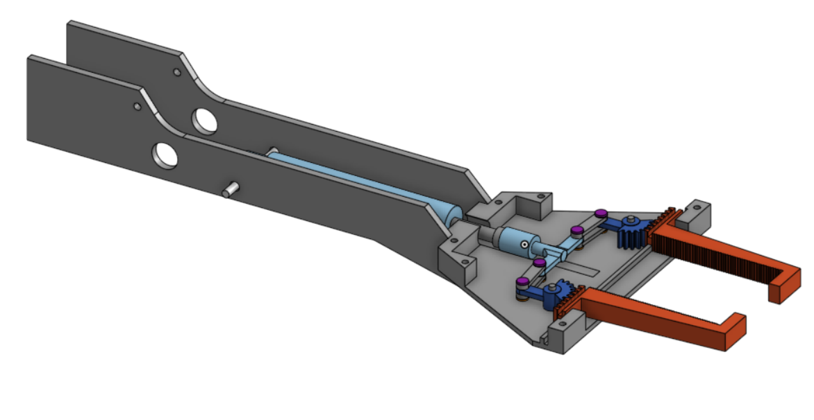
Failed gripper
This was an unsuccessful gripper design that consumed a significant amount of our time. It utilized a round gear and a linear gear to make the orange components slide. However, the design was too large to be 3D printed efficiently.
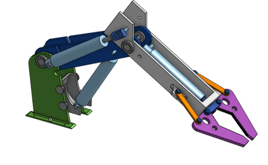
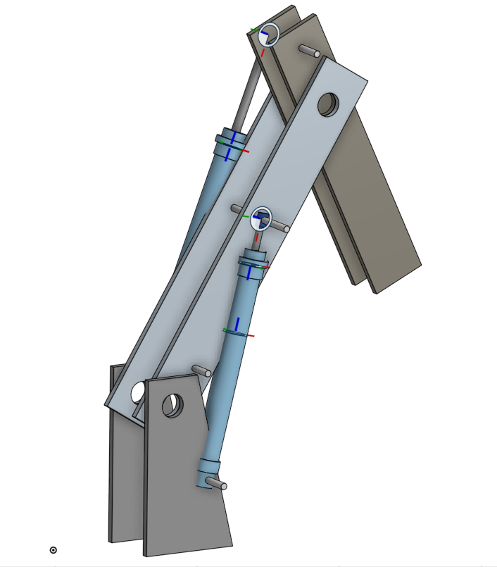
Final assembly
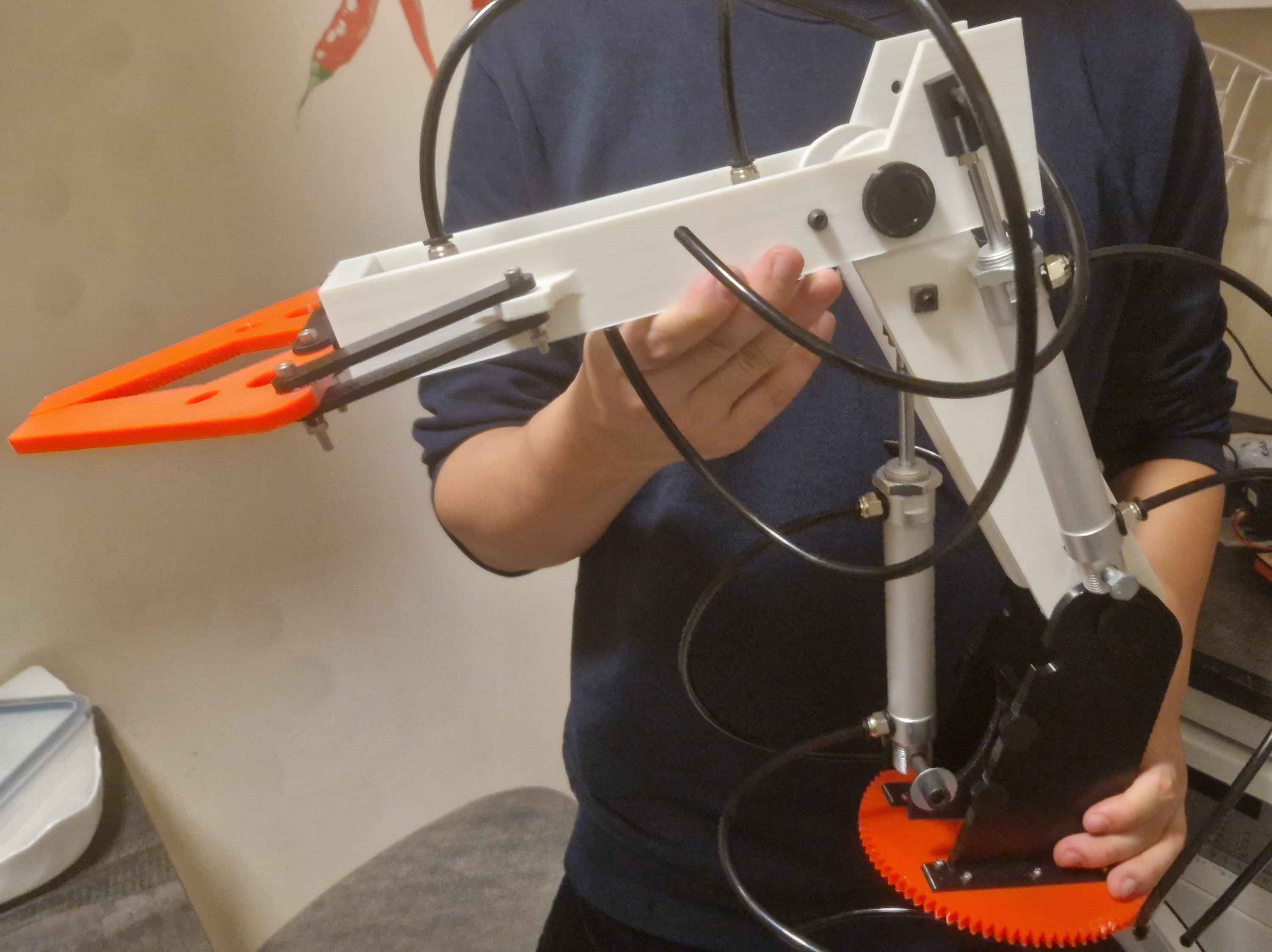
The entire hydraulic arm assembly, including the base, central section, and gripper, is bolted to a large gear. This gear will enables rotational motion of the arm.
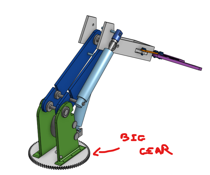
This is the final version of the arm, printed and assembled.
Discussions
Become a Hackaday.io Member
Create an account to leave a comment. Already have an account? Log In.